

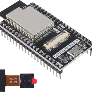
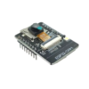
ESP32-CAM WiFi Bluetooth Development Board with OV5640 5MP Camera Module
₹825.00 excl GST
ESP32-CAM board with OV5640 5MP camera, WiFi, Bluetooth, PSRAM, microSD slot and flash LED for IoT imaging projects.
ESP32-CAM WiFi Bluetooth Development Board with OV5640 5MP Camera
The ESP32-CAM WiFi Bluetooth Development Board with OV5640 5MP Camera is a compact wireless camera module suitable for IoT image capture, remote monitoring, robotics vision, time-lapse photography and embedded camera projects. It combines the ESP32 microcontroller with an upgraded OV5640 5MP camera module, making it a better option than standard ESP32-CAM boards that commonly use 2MP OV2640 camera modules.
The onboard ESP32 supports WiFi and Bluetooth connectivity, allowing the board to be used for wireless image streaming, local image capture, web camera projects and cloud-connected IoT applications. The board also includes external PSRAM, which helps in handling higher-resolution camera frames more efficiently.
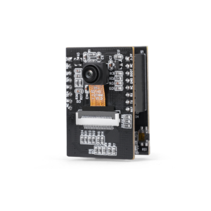
The OV5640 camera module supports up to QSXGA 2592 x 1944 pixel image output. This makes the board useful for applications where improved image clarity is required, such as 3D printer monitoring, smart meter image reading experiments, classroom projects, robotics prototypes and general ESP32 camera development.
A built-in TF / microSD card slot is provided for local image storage. The board also includes an onboard white flash LED connected to GPIO 4, which can be used for basic illumination or flash control in supported projects.
Key Features of ESP32-CAM WiFi Bluetooth Development Board with OV5640 5MP Camera
- ESP32-based WiFi and Bluetooth camera development board
- Upgraded OV5640 5MP camera module
- Supports up to QSXGA 2592 x 1944 pixel image capture
- Built-in WiFi for wireless camera and IoT projects
- Bluetooth 4.2 / BLE support
- 4MB PSRAM for better camera buffer handling
- Built-in TF / microSD card slot
- Onboard white flash LED connected to GPIO 4
- Compact board size for embedded applications
- Supports Arduino IDE programming
- Requires USB-to-TTL serial adapter for programming
- Suitable for students, makers, engineers and IoT developers
Applications
- IoT wireless camera projects
- DIY ESP32 WiFi camera
- 3D printer monitoring
- Time-lapse image capture
- Smart meter image reading experiments
- Robotics vision projects
- Home automation monitoring
- Remote image capture projects
- Classroom and engineering projects
- Embedded camera prototyping
Specifications
| Parameter | Details |
|---|---|
| Product Type | ESP32-CAM WiFi Bluetooth Camera Development Board |
| Microcontroller | ESP32-D0WDQ6 |
| Processor | Dual-core 32-bit CPU, up to 240MHz |
| Wireless | WiFi 802.11 b/g/n + Bluetooth 4.2 / BLE |
| Camera Module | OV5640 |
| Camera Resolution | 5 Megapixel |
| Maximum Image Resolution | QSXGA 2592 x 1944 pixels |
| Sensor Type | 1/4-inch color CMOS |
| Internal SRAM | 520KB |
| External PSRAM | 4MB |
| Storage | Built-in TF / microSD card slot |
| Flash LED | Onboard white LED connected to GPIO 4 |
| Antenna | Onboard PCB antenna |
| External Antenna Option | IPEX / U.FL connector, depending on board batch |
| Programming Interface | USB-to-TTL serial adapter required |
| Recommended Operating Voltage | 5V through 5V pin |
| Logic Level | 3.3V |
| Board Size | Approx. 27mm x 40mm x 4.5mm |
| Arduino IDE Board Selection | AI Thinker ESP32-CAM |
Pinout / Wiring Notes
| Pin / GPIO | Function / Note |
| 5V | Recommended power input |
| 3.3V | 3.3V power pin. Do not connect 5V here |
| GND | Ground |
| U0R / RX0 | UART receive pin for programming |
| U0T / TX0 | UART transmit pin for programming |
| GPIO 0 | Connect to GND during power-up to enter programming mode |
| GPIO 4 | Onboard white flash LED |
| GPIO 1 | UART TX, used during programming and serial output |
| GPIO 3 | UART RX, used during programming |
| GPIO 12, 13, 14, 15 | Commonly used with microSD interface |
| GPIO 16 | Usable in selected projects depending on configuration |
| IPEX / U.FL | External antenna connector, depending on supplied board batch |
Basic Programming Wiring
| ESP32-CAM Pin | USB-to-TTL Adapter Pin |
| 5V | 5V |
| GND | GND |
| U0R / RX0 | TX |
| U0T / TX0 | RX |
| GPIO 0 | GND while uploading code |
Programming Steps
- Connect the ESP32-CAM board to a USB-to-TTL serial adapter.
- Connect GPIO 0 to GND.
- Power the board with a stable 5V supply.
- Open Arduino IDE.
- Select AI Thinker ESP32-CAM board.
- Enable PSRAM in Arduino IDE settings.
- Select the correct COM port.
- Upload the code.
- Remove GPIO 0 from GND after upload.
- Reset or power cycle the board to run the program.
Package Includes
1 x ESP32-CAM WiFi Bluetooth Development Board with OV5640 5MP Camera Module,
Product Disclaimer / Note
Product specifications, PCB color, pinout, board layout, markings, camera connector, antenna type and minor hardware details may vary depending on stock availability or supplier batch. Product images are for representation only. Please verify the actual board and pinout before use in final projects.
Downloads the OV5640 Datasheet here
FAQs
1. What is the main difference between this board and a standard ESP32-CAM?
The main difference is the camera module. Standard ESP32-CAM boards usually come with a 2MP OV2640 camera, while this board comes with an OV5640 5MP camera module for higher image resolution.2. Does this ESP32-CAM board have a USB port?
No. This board does not have a built-in USB port. A separate USB-to-TTL serial adapter is required for programming.3. Which board should I select in Arduino IDE?
Select AI Thinker ESP32-CAM in Arduino IDE. Also enable PSRAM before uploading camera examples.4. How do I enter programming mode?
Connect GPIO 0 to GND before powering or resetting the board. After uploading the code, remove the GPIO 0 to GND connection and reset the board.5. What power supply should I use?
Use a stable 5V power supply. For reliable operation, especially during WiFi streaming or flash LED use, a supply capable of good current output is recommended.6. Why does the camera fail to initialize?
Common reasons include weak power supply, PSRAM not enabled, wrong board selection, incorrect camera pin configuration, loose FPC ribbon cable or wrong camera model selected in code.7. Does this board support microSD card storage?
Yes. It has a built-in TF / microSD card slot for storing images locally.8. Can I use WiFi and microSD card together?
Yes, but performance can reduce because the ESP32 is handling camera capture, WiFi transmission and storage operations at the same time.9. What is the onboard white LED used for?
The onboard white LED can be used as a flash or illumination LED. It is connected to GPIO 4.10. Why does the LED flicker when using the SD card?
On ESP32-CAM boards, GPIO 4 is also associated with microSD operation. Because of this shared function, the flash LED may flicker during SD card access.11. Can I connect an external antenna?
Yes, the board has an IPEX / U.FL antenna connector. However, antenna selection may require changing the tiny onboard resistor position depending on the board configuration.12. Can I power it directly from a 3.7V Li-ion or LiPo battery?
Direct connection is not recommended. Use a proper 5V boost converter or regulated power supply to power the board safely.13. Is the OV5640 camera removable?
Yes. The camera is connected using an FPC ribbon cable. Handle the connector carefully while removing or replacing the camera.14. Are all ESP32 GPIO pins available?
No. Many GPIO pins are used internally by the camera and microSD card interface. Only limited GPIO pins are available for external use.15. Can this board be used for AI or face recognition?
It can be used for basic ESP32 camera experiments and compatible ESP32 camera frameworks. Recommended to use ESP32 AI Vision camera for face recognition applications. Click here to buy. However, performance depends on code, resolution, memory settings and model complexity.Only logged in customers who have purchased this product may leave a review.


Reviews
There are no reviews yet