
Ai-Thinker RD-60-Kit 60GHz mmWave Radar Development and Evaluation Board
₹767.00 incl. GST (₹650.00 + GST)
Product Short Description
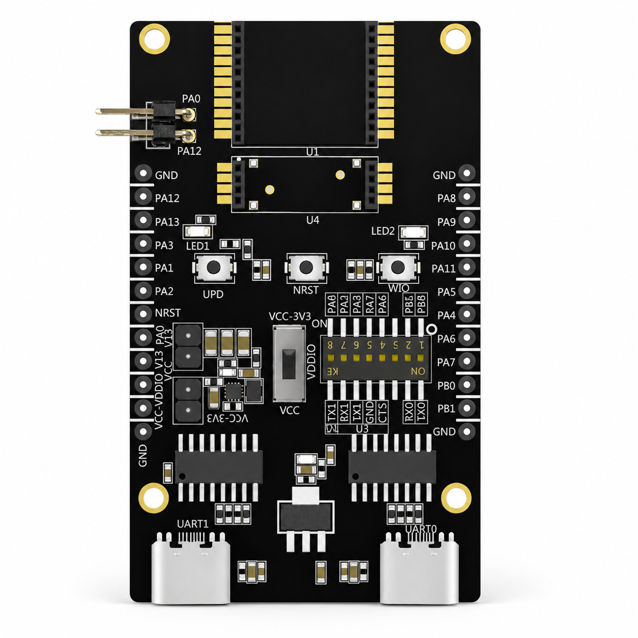
The Ai-Thinker RD-60-Kit is a development and evaluation board for RD-60 and RD-61 60GHz FMCW radar modules. It features dual USB Type-C UART interfaces, TTL communication, onboard status LEDs, control buttons, selectable power options, low-power testing support, radar-module sockets, and GPIO breakout connections for rapid radar application development.
The Ai-Thinker RD-60-Kit is a development and evaluation board designed for testing, configuring, and developing applications using Ai-Thinker’s RD-60 and RD-61 60GHz FMCW millimeter-wave radar modules. It provides an easy-to-use hardware platform with USB Type-C connectivity, UART communication, status indicators, control buttons, selectable power options, and access to the available radar-module interfaces.
The board is particularly useful for developers who want to evaluate human presence detection, motion sensing, micro-motion monitoring, smart lighting, security, home automation, and intelligent appliance applications without designing a custom carrier board at the initial development stage.
The RD-60-Kit includes separate command and radar-data communication interfaces. Its UART0 USB Type-C port is used for sending configuration and control commands, while the UART1 USB Type-C port is used for receiving radar data and communicating with the supported PC host software. This makes parameter configuration, point-cloud data viewing, testing, and firmware development more convenient.
Important Note
RD-60 and RD-61 radar modules are not included with this development board. They must be purchased separately according to your application requirements.
Key Features
- Official evaluation board for Ai-Thinker 60GHz radar modules
- Supports both RD-60 and RD-61 radar modules
- Dedicated sockets for easy radar-module installation
- Two USB Type-C communication interfaces
- Separate UART command and radar-data ports
- Dual TTL serial interfaces
- Supports simultaneous command transmission and data output
- Compatible with supported PC host software
- Suitable for radar point-cloud viewing and parameter adjustment
- Three onboard status indicator LEDs
- Human-presence status indication
- Reset, wake-up, and firmware-burn buttons
- Function-selection DIP switch
- Selectable 3.3V and 5V power configurations
- Supports Type-C and pin-header power input
- Supports low-power-consumption testing
- Breaks out available module GPIO and interface pins
- Compact board size of approximately 42 × 70mm
Product Overview
The RD-60-Kit simplifies the development process by providing the supporting circuitry required to operate and communicate with the compatible radar modules. Developers can mount either an RD-60 or RD-61 module on the corresponding socket, connect the board to a computer using USB Type-C cables, and begin testing the radar output.
The board contains:
- Three onboard LEDs
- Three control buttons
- Two radar-module sockets
- One power-selection switch
- One function-selection DIP switch
- Two USB Type-C interfaces
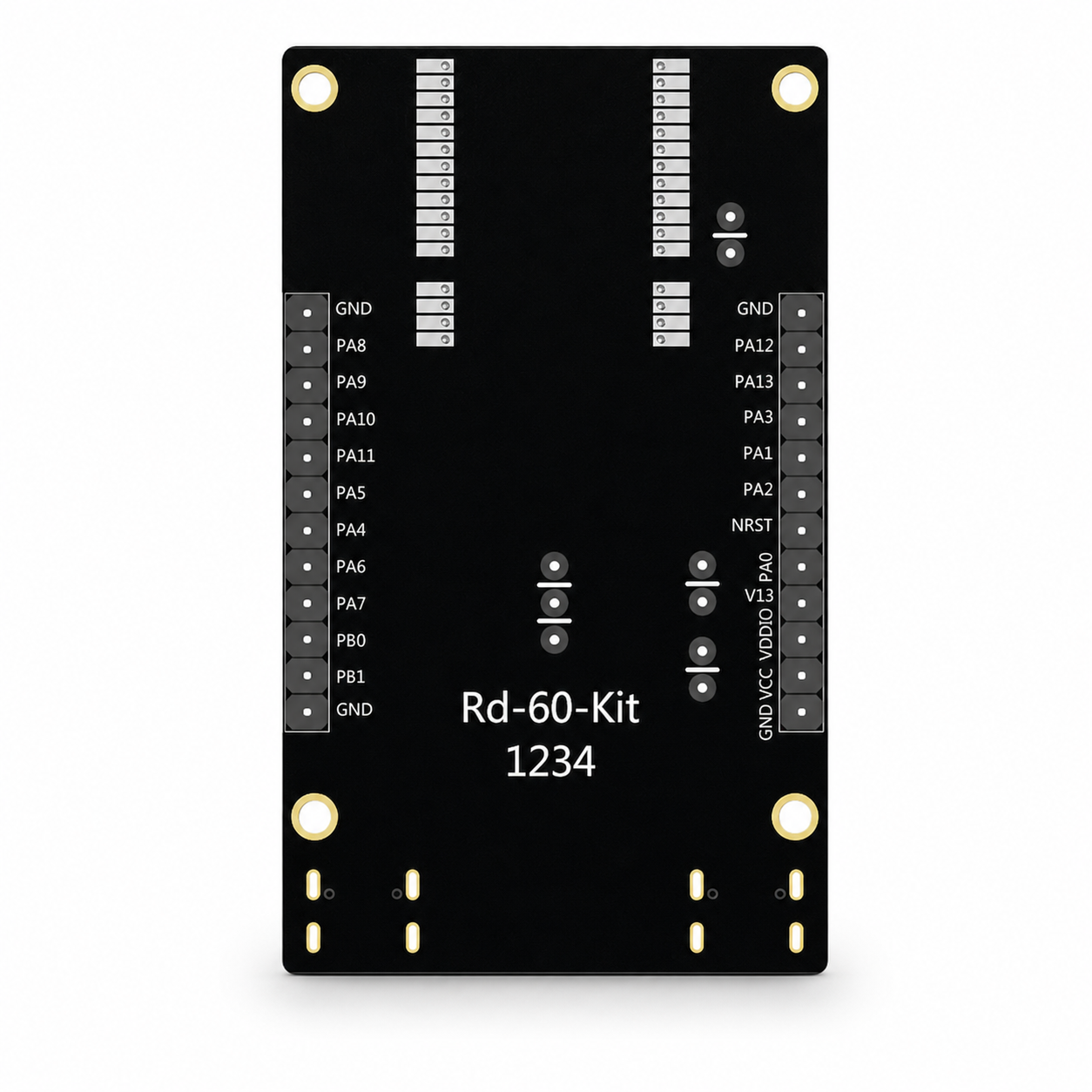
- Dual-row GPIO breakout headers
The board can be used for initial radar evaluation, firmware testing, host-computer communication, low-power measurement, and prototype development.
Technical Specifications
| Parameter | Specification |
|---|---|
| Product Model | RD-60-Kit |
| Product Type | 60GHz radar development and evaluation board |
| Supported Radar Modules | Ai-Thinker RD-60 and RD-61 |
| Board Dimensions | 42 × 70mm, approximately |
| Operating Temperature | -20°C to 70°C |
| Storage Temperature | -40°C to 125°C |
| Storage Humidity | Below 90% RH |
| Supply Voltage Range | 1.7V to 5.5V |
| Typical Supply Voltage | 3.3V |
| Recommended Supply Capability | 500mA or higher |
| USB Interface | 2 × USB Type-C |
| Serial Interfaces | UART0 and UART1 |
| TTL Interfaces | Dual TTL interface |
| Indicator LEDs | 3, red, blue, and green |
| Power Input Methods | USB Type-C or pin header |
| RD-60 Socket | 24-pin female header, 1.27mm pitch |
| RD-61 Socket | 8-pin female header, 1.27mm pitch |
| Control Buttons | Reset, wake-up, and firmware burn |
| Configuration Control | Function-selection DIP switch |
| GPIO Reference Voltage | 3.3V |
USB Type-C Interface Functions
UART0 Command Port
The UART0 Type-C interface is used to send control and configuration commands to the installed radar module. It can be connected directly to a computer using a suitable USB Type-C data cable.
UART1 Radar Data Port
The UART1 Type-C interface is used to receive radar output data. It can communicate with compatible host-computer software for radar-data monitoring, parameter testing, and supported point-cloud display functions.
Both USB connections may require the appropriate USB-to-serial driver to be installed on the computer.
Supported Radar Modules
RD-60 Interface
The RD-60 socket uses a 24-pin female header with 1.27mm spacing. The module must be installed in the correct orientation according to the board markings.
RD-61 Interface
The RD-61 socket uses an 8-pin female header with 1.27mm spacing. It provides a convenient connection for evaluating the compact RD-61 radar module.
Only the compatible radar module should be fitted in its designated socket. Correct orientation must be verified before applying power.
Onboard Indicator LEDs
The board includes three status LEDs:
| Indicator | Function |
|---|---|
| LED1 | Reserved or application-dependent indicator |
| LED2 | Human-presence detection status |
| LED3 | Power indication |
The LED2 connection differs depending on whether an RD-60 or RD-61 module is installed. The board provides an LED-selection interface to configure the correct connection.
Onboard Buttons
Reset Button
The reset button manually resets the installed radar module. The reset input is active low.
Wake-Up Button
The wake-up button is connected to the module’s wake-up GPIO and may be used when the installed module is configured for deep-sleep operation. This is a reserved or firmware-dependent function.
Firmware Burn Button
The burn button is used to place the radar module into firmware programming mode. According to the manufacturer’s procedure, the button must be held while the board is power-cycled or the USB Type-C cable is reconnected. Pressing the reset and burn buttons together may not enter firmware-download mode.
Power-Supply Options
The RD-60-Kit supports two primary power-input methods:
- USB Type-C power supply
- External pin-header power supply
USB Type-C power is recommended for general evaluation and development.
The board also provides selectable power routing for 3.3V and 5V external inputs. The correct switch and jumper configuration must be selected according to the applied input voltage.
For 5V input, the onboard regulated 3.3V supply should be selected. For a regulated 3.3V external supply, the direct VCC option may be used.
Low-Power Testing
The board supports low-power testing for battery-operated and energy-efficient radar applications. The manufacturer specifies an average baseboard consumption of approximately 30.74µA under its stated test conditions.
Reported test values with compatible radar modules include:
| Configuration | Operating State | Typical Average Consumption |
|---|---|---|
| RD-60-Kit baseboard | Without radar activity | 30.74µA |
| With RD-60 | Unoccupied state | 77.82µA |
| With RD-60 | Occupied state | 1.67mA |
| With RD-61 | Unoccupied state | 56.25µA |
| With RD-61 | Occupied state | 1.67mA |
These figures were measured under specific laboratory conditions using low-power firmware and a 3.3V supply. Actual consumption may vary with firmware, communication activity, connected equipment, configuration, and power-supply design.
Typical Applications
- RD-60 radar-module evaluation
- RD-61 radar-module evaluation
- Human-presence detection development
- Stationary-person sensing
- Motion and micro-motion detection
- Radar parameter configuration
- Radar point-cloud testing
- Smart lighting control
- Home and office occupancy monitoring
- Smart appliance development
- Security and intrusion detection
- Elderly-care monitoring prototypes
- Energy-saving automation systems
- Battery-powered radar-device development
- UART and host-computer radar testing
- Firmware programming and debugging
- Academic and research projects
Advantages of Using the RD-60-Kit
The RD-60-Kit removes the need to design a separate carrier PCB during the initial evaluation stage. It provides regulated power options, USB-to-UART communication, module sockets, test indicators, control buttons, and accessible GPIO connections on a single board.
This allows developers to quickly:
- Test RD-60 and RD-61 modules
- Send radar configuration commands
- Receive and monitor radar data
- Change communication routing
- Test human-presence indication
- Measure low-power performance
- Program compatible module firmware
- Connect external peripherals
- Develop proof-of-concept applications
Package Includes
- 1 × Ai-Thinker RD-60-Kit Radar Development Board
Download Datasheet Here
Important Package Note
The RD-60 or RD-61 radar module is not included unless specifically mentioned in the product package or selected product variation. Radar modules, USB Type-C data cables, programmers, external sensors, jumper wires, and other accessories may need to be purchased separately.
Product Disclaimer
Images are for representation only. The actual PCB colour, component placement, markings, switches, connectors, included accessories, and hardware revision may vary depending on the available manufacturing batch.
The development board must be configured correctly before applying power. Incorrect jumper placement, reversed module installation, unsuitable voltage, incorrect switch selection, or improper firmware programming may damage the board or radar module.
Host-computer software compatibility, point-cloud functions, output format, and available configuration options may depend on the installed radar module and firmware version. Specifications are subject to revision by the manufacturer.
Related Radar and UWB Products
Compare this module with related radar sensors, mmWave modules and development boards available from Robosap.
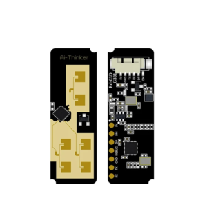
- Ai-Thinker RD-60 60GHz FMCW mmWave Radar Module with BLE 5.3
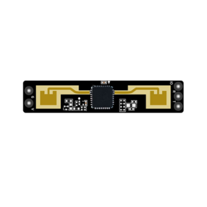
- Ai-Thinker RD-61 60GHz FMCW mmWave Radar Sensor Module
- HLK-LD1125H-24G 24GHz Human Presence Radar Sensor – FMCW Breathing and Motion Detection
- Browse all Radar and UWB modules
Downloads and Documentation
Use these manufacturer or reference documents to verify the exact specifications, pin details, firmware support and integration requirements before designing your system.
Documents may be updated by the manufacturer. Always confirm critical electrical and mechanical details with the latest official documentation before production use.
Downloads and Documentation
Use these manufacturer or reference documents to verify the exact specifications, pin details, firmware support and integration requirements before designing your system. Documents may be updated by the manufacturer. Always confirm critical electrical and mechanical details with the latest official documentation before production use.Only logged in customers who have purchased this product may leave a review.


Reviews
There are no reviews yet