
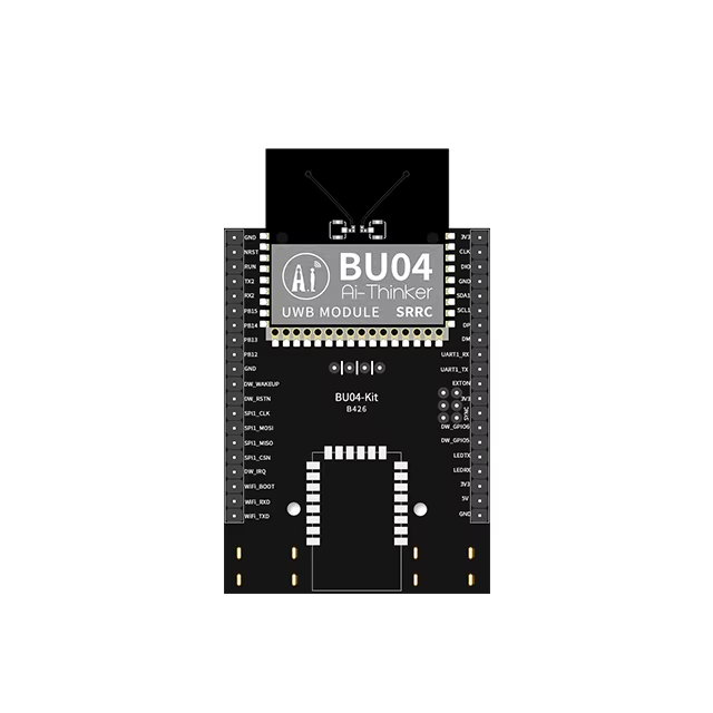
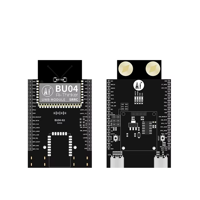
Ai-Thinker BU04-Kit Dual-Antenna UWB Development Board – DW3000 + STM32F103
₹3,353.56 incl. GST (₹2,842.00 + GST)
Ai-Thinker BU04-Kit UWB Development Board is a high-precision indoor positioning platform featuring the DW3000 UWB chip and STM32F103 MCU. Supporting TWR, TDOA, and PDOA, up to 10cm positioning accuracy, 850Kbps/6.8Mbps data rates, SPI, UART, I2C, and dual-antenna options, it is ideal for robotics, RTLS, asset tracking, indoor navigation, and industrial IoT applications.
Ai-Thinker BU04-Kit High-Precision UWB Development Board – DW3000 + STM32F103
Product Description
The Ai-Thinker BU04-Kit is a high-precision Ultra-Wideband (UWB) development board designed for accurate indoor positioning, ranging, wireless communication, and real-time location applications. Built around the DW3000 UWB chip with an integrated STM32F103 microcontroller, the board provides a ready-to-use platform for developing UWB positioning and data-communication systems.
The BU04-Kit is designed for applications requiring high positioning accuracy and supports advanced UWB positioning technologies including Two-Way Ranging (TWR), TDOA, and PDOA. With positioning accuracy of up to approximately 10 cm, it is suitable for applications where conventional Bluetooth or Wi-Fi positioning may not provide sufficient precision.
The board supports UWB Channel 5 and Channel 9, with operating frequencies of 6489.6 MHz and 7987.2 MHz respectively. It also supports configurable data rates of 850 Kbps and 6.8 Mbps, providing flexibility for both positioning and high-speed UWB data transmission.
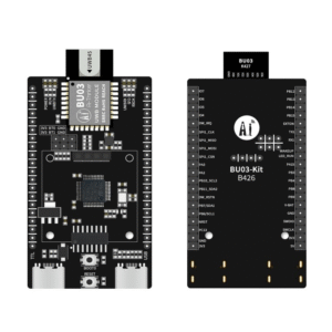
With a DIP-40 style development format, multiple communication interfaces, onboard antennas, and support for external IPEX antennas, the BU04-Kit is convenient for laboratory testing, prototyping, robotics, industrial positioning, asset tracking, and other UWB development projects.
Features
- High-precision UWB development board
- Based on DW3000 UWB technology
- Integrated STM32F103 MCU
- Supports TWR, TDOA, and PDOA positioning methods
- Positioning accuracy up to approximately 10 cm
- Supports UWB Channel 5 and Channel 9
- Channel 5 frequency: 6489.6 MHz
- Channel 9 frequency: 7987.2 MHz
- Supports 850 Kbps and 6.8 Mbps data rates
- Dual-antenna UWB design
- Onboard PCB antennas
- Supports external IPEX antennas
- Built-in HW AES-256 security
- DIP-40 development format
- SPI communication interface
- UART communication interface
- I2C communication interface
- 20 GPIOs
- USB Type-C interface
- Supports 3.3V and 5V power input options
- Suitable for indoor positioning and ranging
- Designed for industrial and embedded applications
Specifications
| Parameter | Specification |
|---|---|
| Product Type | UWB Development Board |
| Model | BU04-Kit |
| UWB Chip | DW3000 |
| Integrated MCU | STM32F103 |
| Positioning Accuracy | Up to 10 cm |
| Frequency Channel | CH5 / CH9 |
| CH5 Frequency | 6489.6 MHz |
| CH9 Frequency | 7987.2 MHz |
| Data Rate | 850 Kbps / 6.8 Mbps |
| Power Supply | 3.3V – 5.0V |
| Power Interfaces | USB Type-C, 3.3V Pin, 5V Pin |
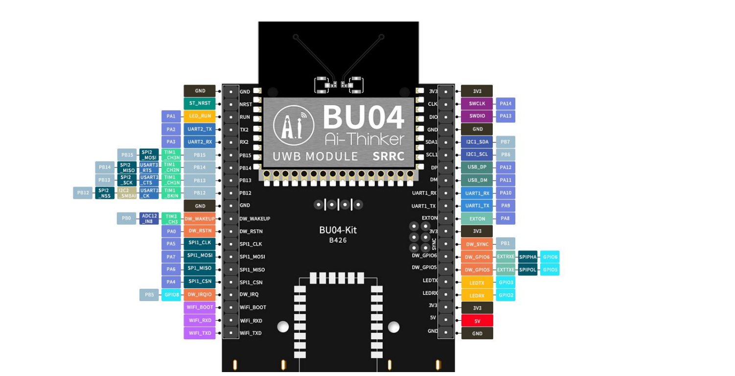
| Interfaces | SPI, UART, I2C |
| GPIO | 20 |
| Antenna | Onboard PCB Antenna / IPEX External Antenna |
| Security | HW AES-256 |
| Dimensions | 46.00 × 52.00 mm (±0.2 mm) |
| Operating Temperature | -40°C to 85°C |
| Transmit Current | Approximately 43–53 mA |
Working Principle
The BU04-Kit uses Ultra-Wideband radio technology to transmit and receive very short-duration radio pulses with precise timing information.
By measuring the time required for signals to travel between UWB devices, the system can calculate distance with high accuracy. These distance measurements can then be used with supported positioning methods to determine the location of a tag, anchor, or moving device.
The onboard STM32F103 MCU provides the processing and control functions required for communication with the UWB chipset and external systems.
The actual positioning accuracy depends on the environment, antenna setup, calibration, device placement, multipath effects, synchronization, firmware, and application configuration.
UWB Positioning Technologies
Two-Way Ranging (TWR)
TWR determines the distance between UWB devices by exchanging signals and calculating the time required for communication. It is commonly used for indoor distance measurement and positioning systems.
Time Difference of Arrival (TDOA)
TDOA determines device position by comparing the arrival times of UWB signals at multiple reference anchors. It is useful for tracking multiple mobile tags in larger positioning installations.
Phase Difference of Arrival (PDOA)
PDOA uses phase information between antenna paths to estimate direction and improve positioning performance.
Dual-Antenna Design
The BU04-Kit is designed with a dual-antenna configuration to support advanced positioning and direction-related applications.
It provides onboard PCB antenna options and also supports compatible IPEX external antennas, giving developers flexibility when designing systems with different enclosure, range, or antenna-placement requirements.
Communication Interfaces
The board provides multiple interfaces for connecting the UWB module to external controllers and devices:
SPI
SPI can be used for high-speed communication with compatible devices and UWB control systems.
UART
UART provides a simple serial interface for configuration, communication, debugging, and interaction with external processors.
I2C
I2C can be used for communication with compatible peripherals and system components.
GPIO
The board provides 20 GPIOs, allowing users to connect external sensors, indicators, triggers, and control signals.
Power Supply
The BU04-Kit supports a supply range of 3.3V to 5.0V and provides multiple power-input options through:
- USB Type-C
- 3.3V pin
- 5V pin
Use the appropriate power input according to the board documentation and avoid applying incompatible voltages simultaneously.
Security
The module supports hardware AES-256 encryption, making it suitable for applications where secure wireless communication and data protection are important.
This feature can be useful in industrial tracking, access control, asset monitoring, and other applications where wireless data should be protected.
Typical Application Scenarios
Indoor Positioning
Suitable for high-precision indoor positioning of people, robots, equipment, and assets where centimeter-level accuracy is required.
Robotics
Can be used for robot localization, navigation, formation control, autonomous movement, and robot-to-robot ranging.
Asset Tracking
Suitable for tracking tools, equipment, industrial assets, and mobile objects within warehouses, factories, and other controlled environments.
Industrial Positioning
Useful for indoor positioning systems in factories, logistics centres, warehouses, production areas, and industrial automation environments.
Real-Time Location Systems
The board can be used as a development platform for RTLS applications involving anchors and mobile tags.
Applications
- UWB indoor positioning
- Real-time location systems (RTLS)
- Indoor navigation
- Robot localization
- Autonomous robotics
- Asset tracking
- Warehouse tracking
- Industrial automation
- Personnel tracking
- Equipment monitoring
- Anchor and tag development
- Distance measurement
- UWB ranging
- Smart factory systems
- Logistics monitoring
- IoT positioning
- Secure wireless communication
- Embedded UWB projects
- Research and development
- UWB prototyping
Package Includes
- 1 × Ai-Thinker BU04-Kit UWB Development Board
- Protective Packaging (Foam + Electrostatic Bag)
Datasheet
Download the Ai-Thinker BU04-Kit Datasheet
Product Disclaimer
The specifications provided are based on the manufacturer’s stated information and laboratory test conditions. Actual positioning accuracy, communication range, current consumption, and system performance may vary depending on antenna configuration, installation environment, firmware, surrounding objects, interference, calibration, and operating conditions.
Product images are shown for illustrative and representational purposes only. The actual board may vary slightly in PCB colour, component placement, antenna layout, connector arrangement, dimensions, or other visual details depending on the manufacturing batch or hardware revision.
Ai-Thinker may update hardware specifications, firmware, documentation, or product details without prior notice.
Important Notes
ESD Protection
The BU04-Kit is an electrostatic-sensitive device. Handle the board using appropriate ESD precautions and avoid touching exposed electronic contacts unnecessarily.
Antenna Installation
For reliable UWB performance, avoid placing large metal objects or other RF-obstructing materials close to the antenna area.
External antenna selection and placement can significantly affect range, positioning accuracy, and overall system performance.
Positioning Accuracy
The stated 10 cm accuracy is a nominal capability under suitable conditions. Real-world accuracy can be affected by multipath reflections, antenna orientation, synchronization, line-of-sight conditions, installation height, and environmental interference.
Power Input
Use a suitable 3.3V–5V power source according to the selected input interface. Follow the manufacturer’s documentation carefully when using the 3.3V or 5V pins.
Related UWB Modules
Compare this product with related UWB modules and development boards available from Robosap.
- Ai-Thinker BU04 dual-antenna UWB module
- Ai-Thinker BU03-Kit UWB development board
- Radar and UWB modules category
Downloads and Documentation
Use these manufacturer or reference documents to verify specifications, pin details, firmware support and integration requirements before designing your system.
Documents may be updated by the manufacturer. Always confirm critical electrical and mechanical details with the latest official documentation before production use.
Frequently Asked Questions
1. What is the Ai-Thinker BU04-Kit?
The BU04-Kit is a high-precision UWB development board based on the DW3000 UWB chipset and an integrated STM32F103 MCU.
2. What positioning accuracy can it achieve?
The specified positioning accuracy is up to approximately 10 cm under suitable conditions.
3. Which UWB channels are supported?
The board supports Channel 5 and Channel 9.
4. What are the operating frequencies?
Channel 5 operates at 6489.6 MHz, while Channel 9 operates at 7987.2 MHz.
5. Which positioning methods are supported?
The board supports TWR, TDOA, and PDOA positioning technologies.
6. What data rates are available?
The supported data rates are 850 Kbps and 6.8 Mbps.
7. What communication interfaces are available?
The board provides SPI, UART, and I2C interfaces along with 20 GPIOs.
8. Does it support external antennas?
Yes. In addition to onboard PCB antennas, the board supports compatible IPEX external antennas.
9. What microcontroller does it use?
The board includes an STM32F103 MCU for control and processing.
10. Does it support encryption?
Yes. The module includes hardware AES-256 support for secure data communication.
11. What voltage does the board require?
The specified supply range is 3.3V to 5.0V, with USB Type-C, 3.3V pin, and 5V pin power options.
12. Can it be used with robots?
Yes. It is suitable for robot localization, navigation, ranging, tracking, and indoor positioning applications.
13. Can it be used for asset tracking?
Yes. UWB is well suited to high-accuracy indoor tracking of equipment, tools, tags, and mobile assets.
14. What is the board size?
The approximate dimensions are 46 × 52 mm, with a stated tolerance of ±0.2 mm.
15. What is the operating temperature range?
The specified operating temperature range is -40°C to 85°C.
16. Is the board suitable for production systems?
It is primarily a development and prototyping platform. Thorough testing, calibration, RF evaluation, and system validation should be completed before deploying it in a production or safety-critical system.
17. Does the package include an external antenna?
No. The package includes the BU04-Kit development board and protective packaging. External antennas are not included unless specifically stated.
18. Does the board require ESD protection during handling?
Yes. The BU04-Kit is an electrostatic-sensitive device, so suitable ESD handling precautions should be followed.Downloads and Documentation
Use these manufacturer or reference documents to verify specifications, pin details, firmware support and integration requirements before designing your system. Documents may be updated by the manufacturer. Always confirm critical electrical and mechanical details with the latest official documentation before production use.Product Disclaimer
Images are for representation only. Actual product appearance, PCB marking, connector style, antenna layout, colour, pin-header configuration or included accessories may vary depending on the available production batch. Product description information listed here is collected from different internet sources, manufacturer pages, datasheets and reference documents, and may contain mistakes or become outdated. Always verify critical electrical, mechanical, firmware and safety details from the latest official manufacturer documentation before design, production or field installation. Radar, mmWave and UWB sensing performance depends on firmware, configuration, power supply quality, installation height, antenna direction, enclosure material, target size, target movement, reflections, interference, line-of-sight and surrounding environment. Distance, angle, accuracy and current values are reference values unless explicitly guaranteed by the latest manufacturer datasheet for the exact supplied revision.Only logged in customers who have purchased this product may leave a review.



Reviews
There are no reviews yet