
MCP2515 CAN Bus Module with TJA1050 Transceiver – SPI Interface
₹109.74 incl. GST (₹93.00 + GST)
The MCP2515 CAN Bus Module with TJA1050 Transceiver adds CAN 2.0B communication to Arduino and other SPI-compatible microcontrollers. It supports communication speeds up to 1 Mbps, standard and extended CAN frames, and data fields up to 8 bytes. Featuring a 5V power input, SPI interface, INT pin, CANH/CANL connections, and selectable 120Ω termination, it is suitable for automotive prototyping, industrial automation, robotics, and embedded CAN communication projects.
1. Product Description
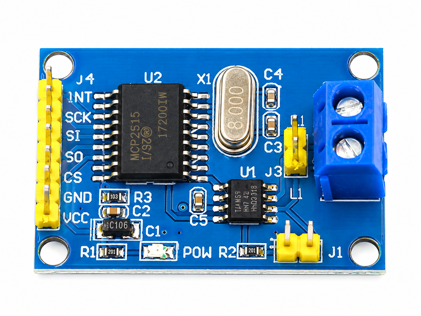
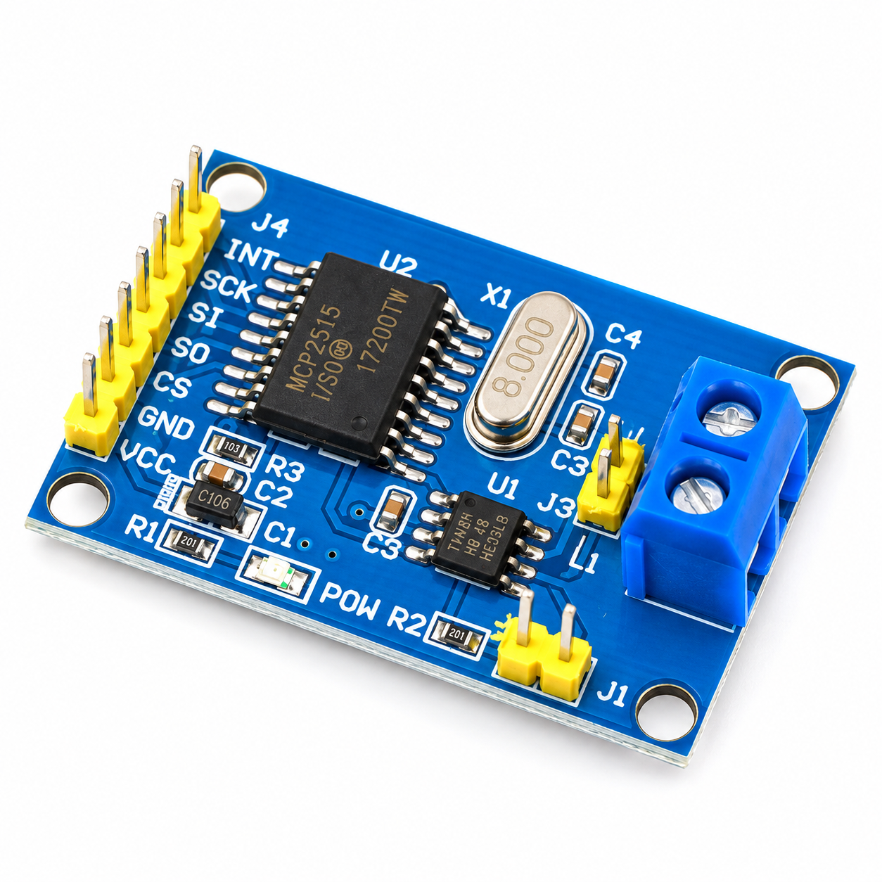
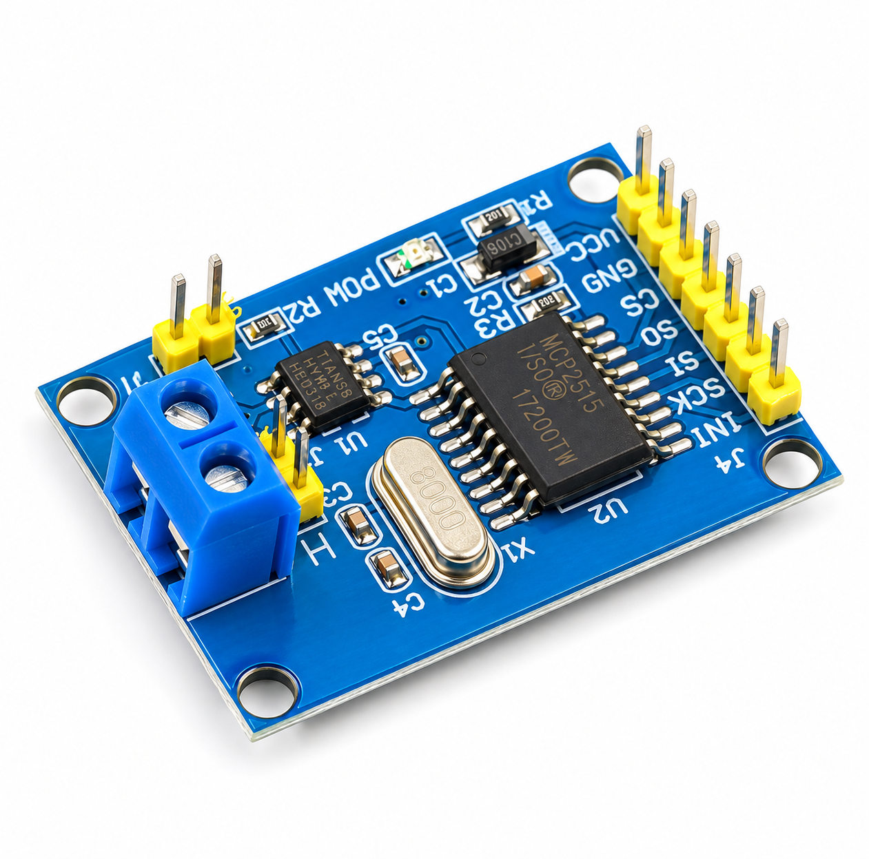
The MCP2515 CAN Bus Module with TJA1050 Transceiver is a compact communication module designed to add Controller Area Network (CAN) functionality to microcontrollers and embedded systems through an SPI interface. It combines the MCP2515 standalone CAN controller with the TJA1050 high-speed CAN transceiver, enabling communication between compatible devices over a CAN bus.
The module is suitable for Arduino UNO and other compatible microcontroller projects that require reliable communication between multiple electronic devices. It supports the CAN 2.0B protocol, including standard frames, extended frames, and remote frames, with data fields of up to 8 bytes and communication rates of up to 1 Mbps.
The SPI interface simplifies integration with microcontrollers, while the onboard CANH and CANL connections allow the module to connect to a CAN network. It also features a selectable 120Ω termination resistor, an interrupt output, LED indicators, and mounting holes for convenient installation.
With its compact design and support for high-speed CAN communication, the MCP2515 module is suitable for automotive electronics, industrial automation, robotics, embedded control systems, and CAN-based communication projects.
2. Features
-
MCP2515 standalone CAN controller
-
TJA1050 high-speed CAN transceiver
-
Supports the CAN 2.0B communication standard
-
Communication speed of up to 1 Mbps
-
SPI interface for communication with a microcontroller
-
Supports standard, extended, and remote CAN frames
-
Data field length of 0–8 bytes per CAN frame
-
CANH and CANL bus connections
-
Selectable 120Ω termination resistor through J1
-
Two CAN bus connection options: KF301-2P terminal block and pin output
-
INT interrupt output for controller notification
-
Onboard LED indicators and independent key, as specified
-
Power connection pins for convenient integration
-
Mounting holes with 23 mm × 38 mm center spacing
-
Suitable for Arduino and other compatible SPI-enabled controllers
3. Specifications
| Specification | Details |
|---|---|
| Product Name | MCP2515 CAN Bus Module |
| CAN Controller | MCP2515 |
| CAN Transceiver | TJA1050 |
| Communication Protocol | CAN 2.0B |
| Maximum Communication Rate | Up to 1 Mbps |
| Interface to MCU | SPI |
| CAN Frame Types | Standard, Extended, Remote |
| CAN Data Field | 0–8 bytes |
| Power Input | 5V DC |
| Typical Working Current | Approximately 5 mA, as specified |
| Standby Current | Approximately 1 µA, as specified, excluding power indicator |
| CAN Signals | CANH and CANL |
| Termination | Selectable 120Ω resistor |
| Interrupt Pin | INT |
| Mounting Hole Center Spacing | 23 mm × 38 mm |
| Compatible Platforms | Arduino UNO and compatible microcontrollers |
| Package Includes | 1 × MCP2515 CAN Bus Module |
Note: Actual current consumption depends on the module revision, LED circuit, transceiver state, and connected CAN bus. Confirm electrical specifications for the exact board before finalizing a design.
4. Working Principle
The module uses two main integrated circuits to provide CAN communication.
MCP2515 CAN Controller: The MCP2515 handles CAN protocol functions, including message formatting, frame transmission, reception, and error management. It communicates with the host microcontroller through SPI.
TJA1050 CAN Transceiver: The TJA1050 converts the controller’s digital CAN signals into the differential electrical signals used on the CAN bus and converts received bus signals back into logic-level signals for the controller.
When a microcontroller sends a message through SPI, the MCP2515 processes the message and passes it to the TJA1050 for transmission over the CANH and CANL lines. Incoming CAN messages are received by the transceiver and processed by the MCP2515, which can notify the microcontroller through the INT pin.
This arrangement allows microcontrollers without an integrated CAN controller to participate in compatible CAN networks.
5. Pin Definitions
| Pin | Function | Description |
|---|---|---|
| VCC | Power | 5V DC power input |
| GND | Ground | Power ground |
| CS | SPI Chip Select | Selects the MCP2515 for SPI communication |
| SO | SPI MISO | Serial output from the module to the MCU |
| SCLK | SPI Clock | SPI clock signal |
| INT | Interrupt | Signals the MCU when attention is required |
Important: The supplied pin list does not include all possible SPI signals. The module also requires an SPI data input connection, generally identified as SI or MOSI, on the actual board. Check the board’s silkscreen and pinout before wiring.
6. Interface and Connections
The module provides several connection options:
-
J1 – 120Ω termination selection: Enables or disables the onboard termination resistor, depending on the board’s jumper arrangement.
-
J2 – CAN terminal block: Provides CANH and CANL connections through the KF301-2P terminal block.
-
J3 – CAN pin output: Provides another connection point for CANH and CANL.
The termination resistor should be configured according to the CAN network topology. In a typical properly terminated CAN bus, 120Ω termination is placed at each physical end of the bus, not at every node.
7. SPI Communication
The module communicates with the host microcontroller using the Serial Peripheral Interface (SPI). The microcontroller configures the MCP2515, sends CAN messages, and reads received messages through this interface.
Common compatible platforms include:
-
Arduino UNO
-
Arduino Mega
-
Other Arduino-compatible boards with suitable SPI support
-
Embedded systems with compatible SPI interfaces
Software libraries compatible with the MCP2515 can simplify initialization, message transmission, reception, and interrupt handling.
8. CAN 2.0B Protocol Support
The module supports CAN 2.0B functionality, including:
-
Standard frames: Messages using the standard 11-bit identifier.
-
Extended frames: Messages using the extended 29-bit identifier.
-
Remote frames: Frames used to request data from another CAN node.
-
Data fields: Up to 8 bytes per classic CAN data frame.
-
Communication speed: Up to 1 Mbps, depending on bus length, wiring, and network configuration.
This makes the module suitable for exchanging control commands, sensor readings, status information, and other embedded-system data.
9. Termination Resistor
The onboard 120Ω resistor helps match the impedance of the CAN bus and reduce signal reflections.
For a typical linear CAN bus, termination resistors are installed at the two physical ends of the network. If the module is connected at one of those ends, its onboard termination may be enabled. If it is an intermediate node, the termination is normally disabled.
Incorrect termination can cause communication errors, especially at higher data rates.
10. Applications
The MCP2515 CAN Bus Module is suitable for:
-
Automotive electronics prototyping
-
Industrial automation
-
Robotics and mobile robots
-
CAN-based sensor networks
-
Embedded communication systems
-
Motor controller communication
-
Battery monitoring prototypes
-
Vehicle telemetry projects
-
Arduino CAN bus projects
-
Distributed control systems
-
Data acquisition systems
-
CAN protocol learning and experimentation
11. Package Includes
– 1 × MCP2515 CAN Bus Module with TJA1050 Transceiver
Microcontroller boards, connecting wires, CAN cables, power supplies, and other accessories are not included unless explicitly specified.
12. Product Disclaimer
-
This module supports classic CAN 2.0B, not CAN FD.
-
The stated maximum speed of 1 Mbps depends on bus length, wiring quality, termination, and network configuration.
-
The module requires a compatible SPI interface and suitable software.
-
Verify the board’s complete pinout before wiring; the supplied pin list does not explicitly identify the SPI MOSI/SI pin.
-
Use the correct power supply and ensure that connected logic signals are electrically compatible.
-
Configure the termination resistor according to the physical CAN bus layout.
-
This is a CAN communication module, not a complete standalone CAN system.
Note: Product images are for illustration and representation purposes only. The actual product may slightly differ in appearance, colour, design, or component placement from the images shown due to manufacturing variations and production batches.
Frequently Asked Questions (FAQs)
1. What is the MCP2515 CAN Bus Module?
It is a CAN communication module that combines the MCP2515 CAN controller and TJA1050 transceiver to enable CAN bus communication through an SPI interface.2. What is the MCP2515 used for?
The MCP2515 handles CAN protocol operations such as message transmission, reception, frame processing, and error management.3. What is the TJA1050 used for?
The TJA1050 is a CAN transceiver that converts digital CAN controller signals into the differential electrical signals required by the CAN bus.4. What is the maximum communication speed?
The supplied specification states a maximum communication speed of 1 Mbps.5. Which CAN protocol does it support?
It supports CAN 2.0B, including standard and extended frames.6. Does it support CAN FD?
No. The MCP2515 supports classic CAN 2.0B and does not support CAN FD.7. What is the maximum data length per frame?
Classic CAN data frames support up to 8 bytes of data.8. Does it support standard CAN frames?
Yes. It supports standard CAN frames with 11-bit identifiers.9. Does it support extended CAN frames?
Yes. It supports extended CAN frames with 29-bit identifiers.10. Does it support remote frames?
Yes. Remote frames are supported by the classic CAN protocol.11. What interface does it use to communicate with a microcontroller?
It uses the SPI interface.12. Is it compatible with Arduino UNO?
Yes. It is suitable for Arduino UNO and other compatible microcontrollers that support SPI.13. Can it work with Arduino Mega?
Yes. It can be used with an Arduino Mega when the SPI connections, chip-select configuration, and software library are set correctly.14. Can it work with ESP32?
Yes. It can be connected to an ESP32 through SPI, provided the logic levels and wiring are compatible. Verify the module's electrical requirements before connecting it.15. What is the module's operating voltage?
The supplied specifications state a 5V DC power input.16. What are CANH and CANL?
CANH and CANL are the two differential signal lines used to transmit data over the CAN bus.17. What is the purpose of the INT pin?
The INT pin provides an interrupt signal to the host microcontroller when the MCP2515 requires attention, such as when a message is received.18. What does the CS pin do?
CS is the SPI chip-select pin. It selects the MCP2515 for communication with the host microcontroller.19. What do SO and SCLK mean?
SO is the SPI serial output from the module to the microcontroller, while SCLK carries the SPI clock signal.20. Is the MOSI pin required?
Yes. SPI communication normally requires a MOSI or SI signal for data sent from the microcontroller to the MCP2515. Check the actual module pinout because it is not included in the supplied six-pin list.21. What is the J1 interface?
J1 is identified as the termination-resistor selection point for the onboard 120Ω resistor.22. What is the purpose of the 120Ω resistor?
It terminates the CAN bus to help reduce signal reflections and maintain reliable communication.23. Should every CAN module have its termination resistor enabled?
No. In a typical linear CAN network, termination is installed at the two physical ends of the bus. Intermediate nodes generally should not have termination enabled.24. What is the J2 connector?
J2 provides CANH and CANL connections through the KF301-2P terminal block.25. What is the J3 connector?
J3 provides another CANH and CANL connection point through pin output.26. Can multiple CAN modules communicate with each other?
Yes. Multiple compatible CAN nodes can communicate over a properly wired and configured CAN bus.27. Can I use it for automotive projects?
Yes. It is suitable for automotive electronics prototyping and CAN communication experiments. It should not be assumed to be automotive-certified for safety-critical vehicle use.28. Can it be used for industrial automation?
Yes. It can be used in compatible industrial automation and distributed control prototypes.29. Can it communicate with motor controllers?
Yes, if the motor controller supports a compatible CAN protocol, message format, bitrate, and electrical interface.30. Can it be used for battery monitoring?
Yes. It can be used in battery monitoring prototypes when the battery management system provides compatible CAN communication.31. Does the module include an onboard LED?
The supplied specifications mention LED indicators, including a power indicator and a communication-related indicator. The exact indicator functions may vary by board revision.32. Does it have a reset button?
The supplied information mentions an independent key but does not specify its exact function. Verify the board markings to determine whether it is a reset or another control button.33. What is the typical working current?
The supplied specification states approximately 5 mA typical, though actual consumption depends on the board circuitry and operating conditions.34. What is the standby current?
The supplied specification states approximately 1 µA in standby, excluding the power indicator. Actual board-level current may be higher depending on its circuitry.35. Does the module include a microcontroller?
It includes the MCP2515 CAN controller and TJA1050 transceiver, but it does not replace the host microcontroller required to control the module.36. Does it require a software library?
A compatible software library or driver is generally required to configure the MCP2515 and transmit or receive CAN messages from a microcontroller.37. Can I view CAN communication data through a serial monitor?
Yes. A compatible microcontroller program can read CAN messages from the module and print the data through its serial interface for debugging.38. Does the package include an Arduino board?
No Arduino board is listed in the supplied package contents.39. Are connecting wires and CAN cables included?
They are not listed in the supplied package contents and should not be assumed to be included.40. What is included in the package?
The package includes 1 × MCP2515 CAN Bus Module with TJA1050 Transceiver.41. What is the mounting hole spacing?
The specified mounting hole center spacing is 23 mm × 38 mm.42. What causes CAN communication errors?
Common causes include incorrect bitrate, improper termination, wiring mistakes, missing common ground where required, incompatible message settings, and electrical noise.43. Can the module communicate over long distances?
CAN can support long-distance communication under suitable conditions, but the achievable distance depends on bitrate, cable characteristics, termination, and the number of connected nodes. The maximum 1 Mbps rate generally requires a shorter bus than lower data rates.44. Can this module be connected directly to CANH and CANL of another device?
Yes, provided the other device uses a compatible CAN physical layer and protocol. Correct polarity, termination, bitrate, and wiring are essential.45. Is the module suitable for beginners?
Yes. It is useful for learning CAN communication, SPI interfacing, Arduino development, and embedded networking.46. What is the main advantage of this module?
It allows microcontrollers without a built-in CAN controller to communicate over a classic CAN 2.0B bus using SPI.Only logged in customers who have purchased this product may leave a review.


Reviews
There are no reviews yet