
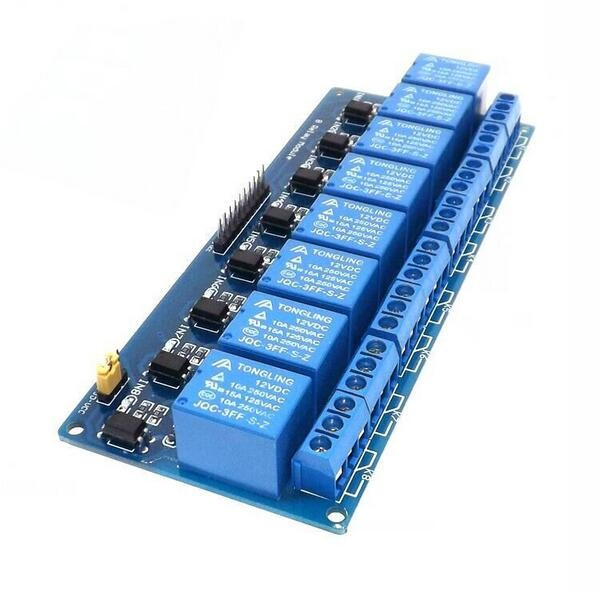
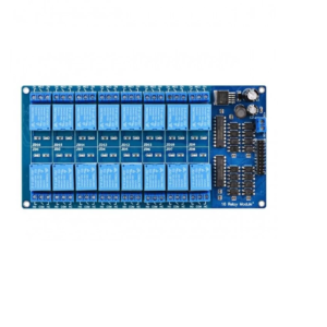
12V 8 Channel Relay Module Board For Arduino Raspberry Pi
₹271.40 incl. GST (₹230.00 + GST)
The 12V 8-Channel Relay Module is a reliable multi-channel switching board designed to control multiple AC or DC loads using Arduino, Raspberry Pi, and other microcontrollers. It features 8 optocoupler-isolated relays, active-low triggering, indicator LEDs, and NO/COM/NC outputs for flexible switching. Each relay supports up to 250V AC/10A or 30V DC/10A, making it suitable for home automation, robotics, industrial control, pumps, motors, lights, and DIY electronics projects.
12V 8-Channel Relay Module with Optocoupler – Low Level Trigger
Product Description
The 12V 8-Channel Relay Module with Optocoupler is a multi-channel relay board designed to control multiple AC or DC electrical loads using a microcontroller or development board. It features 8 independent relay channels with optocoupler isolation, providing reliable switching and improved protection between the control circuit and load section.
The module uses high-current relays capable of switching up to 250V AC at 10A or 30V DC at 10A. Each channel provides NO, COM, and NC contacts, allowing flexible control of normally open and normally closed circuits.
The relay inputs use active-low triggering, making the module easy to interface with popular development platforms. Onboard relay indicator LEDs provide visual feedback when individual channels are activated. The module also includes screw terminals for convenient and secure load connections.
With four mounting holes and a standard control interface, this relay board is suitable for robotics, home automation, industrial control prototypes, Arduino projects, and other applications requiring multiple electrical outputs.
Features
- 8-channel relay module
- 12V relay operation
- Optocoupler isolation
- Low-level trigger inputs
- High-current relay contacts
- Supports up to 250V AC / 10A
- Supports up to 30V DC / 10A
- Independent NO, COM, and NC contacts
- Relay status indicator LEDs
- Convenient screw terminal connections
- Standard interface for development boards
- Four mounting holes for easy installation
- Double-sided FR-4 PCB construction
- Suitable for 51/AVR/ARM and other controller platforms
- 100% function and stability tested
Specifications
| Parameter | Specification |
|---|---|
| Product Type | 8-Channel Relay Module |
| Relay Channels | 8 |
| Relay Voltage | 12V DC |
| Trigger Type | Low Level / Active Low |
| Isolation | Optocoupler |
| AC Switching Rating | 250V AC @ 10A |
| DC Switching Rating | 30V DC @ 10A |
| Control Supply | 5V DC |
| Control Inputs | IN1 – IN8 |
| Output Contacts | NO, COM, NC |
| PCB Material | FR-4 |
| Terminal Type | KF301 Screw Terminal |
| Mounting Holes | 4 |
| Mounting Hole Diameter | 3.1 mm |
| Mounting Hole Pitch | 131 × 49.5 mm |
| Module Dimensions | 138 × 56 × 18.5 mm |
| Weight | Approximately 120 g |
Pin Configuration
| Pin | Function |
|---|---|
| VCC | 5V control power supply |
| GND | Ground |
| IN1 | Relay Channel 1 trigger |
| IN2 | Relay Channel 2 trigger |
| IN3 | Relay Channel 3 trigger |
| IN4 | Relay Channel 4 trigger |
| IN5 | Relay Channel 5 trigger |
| IN6 | Relay Channel 6 trigger |
| IN7 | Relay Channel 7 trigger |
| IN8 | Relay Channel 8 trigger |
Relay Output Configuration
Each relay channel provides three output terminals:
| Terminal | Function |
|---|---|
| NO1 – NO8 | Normally Open contacts |
| COM1 – COM8 | Common relay contacts |
| NC1 – NC8 | Normally Closed contacts |
When the relay is inactive, COM is connected to NC. When the relay is activated, COM switches to NO.
Design and Construction
The module is built using a double-sided FR-4 PCB designed for reliable electrical and mechanical performance. Eight relays are arranged on the board along with optocouplers, driver circuitry, indicator LEDs, and screw terminals.
The blue KF301 screw terminals provide secure and convenient connections for the controlled loads. Four mounting holes allow the module to be securely installed inside enclosures, control panels, robotic systems, and other project structures.
The optocoupler-based control section helps provide electrical isolation between the input/control circuitry and relay switching section, improving resistance to electrical interference.
Working Principle
The module receives control signals through IN1–IN8. Each input independently controls its corresponding relay channel. The inputs are active low, so applying a LOW signal to an input activates the associated relay.
When a relay is activated, its indicator LED turns on and the relay changes its contact state. The COM and NO contacts become connected, allowing the connected load to operate.
When the relay is released, COM returns to its NC connection. This allows each channel to be configured for either normally open or normally closed switching depending on the application.
Usage
- Connect the module’s control supply to the appropriate power source.
- Connect VCC to 5V and GND to the power supply ground.
- Connect the controller’s output pins to IN1–IN8.
- Use the appropriate NO, COM, or NC terminals to connect the loads.
- Apply a LOW-level trigger to the required input to activate its relay.
- Check the corresponding LED to confirm relay activation.
Applications
- Arduino automation projects
- Raspberry Pi control systems
- Home automation
- Industrial automation prototypes
- Multi-load switching
- Lighting control
- Fan control
- Pump control
- Motor control
- Solenoid control
- Robotics
- IoT projects
- Smart control panels
- Electrical appliance switching
- DIY electronics
- Educational projects
Compatible Platforms
- Arduino
- 51 microcontrollers
- AVR
- ARM
- Raspberry Pi
- ESP32
- ESP8266
- STM32
- Other compatible microcontroller and development boards
Package Includes
- 1 × 12V 8-Channel Relay Module with Optocoupler
Product Disclaimer
The relay contact ratings indicate the maximum specified switching capacity and may vary depending on the type of load. Motors, pumps, transformers, and other inductive loads can generate switching transients and may require additional protection.
The control interface uses 5V power, while the relays are rated for 12V operation as specified. Verify the power connections and module configuration before use.
High-voltage AC connections can be hazardous. Use suitable insulation, wiring, fusing, and electrical safety precautions when working with mains-powered loads.
Product images are for representation only. The actual product may differ slightly in appearance, colour, component placement, or terminal configuration depending on the manufacturing batch.
FAQs – 12V 8-Channel Relay Module with Optocoupler
1. What is the 12V 8-Channel Relay Module?
It is an 8-channel relay board used to control multiple AC or DC electrical loads using a microcontroller or development board.
2. How many devices can it control?
It has 8 independent relay channels, allowing up to eight separate loads to be controlled.
3. What type of trigger does the module use?
It uses an active-low trigger, meaning the relay is activated when the corresponding IN pin receives a LOW signal.
4. What is the relay switching capacity?
Each relay supports up to 250V AC at 10A or 30V DC at 10A.
5. What is optocoupler isolation?
Optocoupler isolation electrically separates the control circuit from the relay circuit, helping improve protection and reduce electrical interference.
6. What are IN1 to IN8 used for?
IN1–IN8 are the individual control inputs for Relay Channels 1–8.
7. What are NO, COM, and NC terminals?
- NO: Normally Open
- COM: Common
- NC: Normally Closed
8. What is the function of VCC and GND?
VCC provides the 5V control power supply, while GND connects to the power supply ground.
9. Does the module have status indicators?
Yes. Each relay has an indicator LED that shows when the corresponding relay is activated.
10. Can it be used with Arduino?
Yes. It is suitable for Arduino and other compatible microcontroller platforms with appropriate power and signal connections.
11. Can it be used with ESP32?
Yes, but ensure that the control signal levels and power requirements are compatible with the ESP32 system.
12. What loads can it control?
It can control compatible lights, fans, pumps, motors, solenoids, appliances, and other electrical loads.
13. What is the purpose of NO and NC contacts?
They allow the load to be configured as normally OFF (NO) or normally ON (NC) depending on the required switching behavior.
14. Does the relay module supply power to the load?
No. The relay acts as a switch. The connected load requires its own suitable power supply.
15. Does the module have mounting holes?
Yes. It has four mounting holes for secure installation.
16. What are the dimensions of the module?
The module measures approximately 138 × 56 × 18.5 mm.
17. What are the main applications?
It is suitable for home automation, robotics, IoT, industrial control, lighting, pump control, motor switching, and DIY electronics.
18. What is included in the package?
The package includes 1 × 12V 8-Channel Relay Module with Optocoupler.
19. Can it control high-voltage AC loads?
Yes, within the specified relay rating. High-voltage wiring must be performed using appropriate electrical safety precautions.
20. Can inductive loads such as motors and pumps be connected?
Yes, but inductive loads can generate switching transients and may require suitable protection components depending on the application.
Only logged in customers who have purchased this product may leave a review.



Reviews
There are no reviews yet