
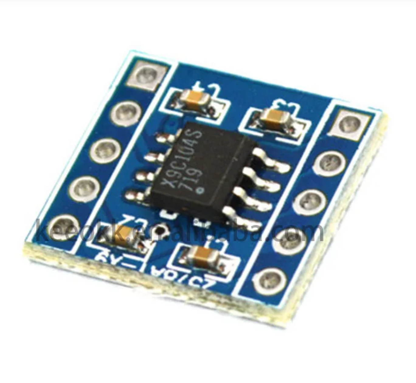
X9C104 Digital Potentiometer Module For Arduino
₹542.80 incl. GST (₹460.00 + GST)
The X9C104 100K Digital Potentiometer Module is a compact digitally controlled variable resistor with 100 selectable resistance steps across a total range of 100kΩ. It uses CS, U/D, and INC control inputs for electronic wiper adjustment and operates from a typical 5V supply. Ideal for programmable voltage dividers, sensor calibration, analog signal adjustment, digital volume control, and Arduino or microcontroller-based projects.
The X9C104 100K Digital Potentiometer Module is a compact and versatile electronic module that provides digitally controlled variable resistance without the need for a traditional mechanical potentiometer. Based on the X9C104 integrated circuit, it uses internal resistor elements and an electronically controlled wiper to provide 100 selectable resistance positions across a total resistance of 100kΩ.
The module can be controlled directly by a microcontroller through the CS, U/D, and INC digital control pins. By applying the appropriate control signals, the wiper position can be moved upward or downward through the available resistance steps, allowing the resistance to be adjusted electronically and repeatedly through software.
With approximately 99 series-connected resistor elements and 100 selectable tap positions, the module provides a linear resistance adjustment with approximately 1kΩ per step. This makes it useful for applications where a variable resistance or programmable voltage divider is required without physically turning a knob.
The X9C104 operates from a typical 5V supply and has a low typical operating current of approximately 3mA. It can be used in electronic experiments, sensor calibration, analog signal adjustment, programmable voltage control, and other microcontroller-based applications.
The module is designed to operate with signals within the applied supply-voltage range. Negative voltages should not be applied to any of the device pins, making proper voltage and signal-level selection important during circuit design.
Features
- Digital potentiometer module based on X9C104
- Total resistance of 100kΩ
- Provides 100 selectable resistance positions
- Approximately 99 internal series-connected resistor elements
- Approximately 1kΩ resistance per step
- Linear resistance adjustment
- Electronic wiper control without mechanical adjustment
- Controlled through CS, U/D, and INC digital inputs
- Typical operating voltage of 5V
- Typical operating current of approximately 3mA
- Suitable for microcontroller-controlled resistance adjustment
- Useful for programmable voltage dividers
- Suitable for analog signal adjustment
- Useful for sensor calibration and tuning
- Suitable for digital volume-control experiments
- Useful for variable-gain circuits
- Compact module design
- Suitable for educational and experimental electronics projects
- Supports resistance adjustment through software control
- No mechanical knob required
Specifications
| Parameter | Specification |
|---|---|
| Product Type | Digital Potentiometer Module |
| IC | X9C104 |
| Total Resistance | 100kΩ |
| Number of Taps | 100 |
| Resistance Per Step | Approximately 1kΩ |
| Adjustment Mode | Linear |
| Operating Voltage | 5V Typical |
| Typical Operating Current | 3mA |
| Control Interface | CS, U/D, INC |
| Operating Temperature | -40°C to +85°C |
| Module Pin Count | 10 Pin Including Breakout Headers |
| Module Dimensions | Approximately 14mm × 15mm × 3mm |
| Application | Variable Resistance, Voltage Control & Calibration |
Design and Construction
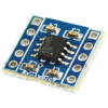
The X9C104 module is built around the X9C104 digital potentiometer IC and provides convenient breakout connections for power, control, and resistor-network terminals.
Internally, the device contains a series of resistor elements connected between the Vh (high) and Vl (low) terminals. The electronically controlled Vw (wiper) terminal can be positioned at different points along this resistor network.
The module provides dedicated control pins for changing the wiper position. CS is used to select or enable the device, U/D determines the direction of resistance adjustment, and INC is used to step the wiper position.
The compact PCB design makes the module suitable for breadboard experiments, embedded prototypes, microcontroller projects, and circuits where a digitally adjustable resistance is required.
Working Principle
The X9C104 operates using an internal resistor network containing approximately 99 series-connected resistance elements. These elements create 100 selectable wiper positions across the total resistance range.
The microcontroller controls the module through the CS, U/D, and INC pins. The U/D input determines whether the wiper moves toward the high or low end of the resistor network, while the INC input advances the wiper by one step when the appropriate control sequence is applied.
By changing the wiper position, the resistance between Vh and Vw or between Vw and Vl can be varied electronically. This allows the module to function similarly to a traditional potentiometer while providing software-controlled adjustment.
For a 100kΩ version, the total resistance is approximately 100kΩ, with the 100 available positions providing approximately 1kΩ change per step.
The module can therefore be connected as a variable resistor or as a programmable voltage divider, depending on the circuit configuration.
The X9C104 operates within the applied supply-voltage range, typically from 0V to Vcc. Negative voltages should not be applied to the device pins.
Pin Interface
| Pin | Name | Function |
| 1 | CS | Chip Select – Enables the device when low |
| 2 | U/D | Controls the direction of resistance change |
| 3 | INC | Steps the wiper position when toggled |
| 4 | Vh | High end of the resistor network |
| 5 | Vw | Adjustable wiper output |
| 6 | Vl | Low end of the resistor network |
| 7 | Vcc | Power supply, typically 5V |
| 8 | GND | Ground connection |
Applications
- Programmable voltage dividers
- Digital volume control
- Electronic volume adjustment
- Sensor calibration
- Sensor sensitivity adjustment
- Analog signal adjustment
- Variable resistance control
- Variable gain amplifier experiments
- Programmable analog circuits
- Microcontroller-controlled resistance
- Electronic tuning circuits
- Analog interface experiments
- Educational electronics projects
- Arduino potentiometer projects
- ESP32 control experiments
- ESP8266 analog-control projects
- Embedded electronics
- Automation projects
- DIY electronics
- Circuit prototyping
- Laboratory experiments
- Electronic calibration systems
- Digital control of analog parameters
- Software-controlled analog adjustment
Package Includes
- 1 × X9C104 100K Digital Potentiometer Module
Pin Interface
| Pin | Name | Function |
|---|---|---|
| 1 | CS | Chip Select – Enables the device when low |
| 2 | U/D | Controls the direction of resistance change (Up/Down) |
| 3 | INC | Steps the wiper position when toggled |
| 4 | Vh | High end of the resistor network |
| 5 | Vw | Adjustable wiper output |
| 6 | Vl | Low end of the resistor network |
| 7 | Vcc | Power supply (5V) |
| 8 | GND | Ground connection |
// X9C104 Digital Potentiometer Example Code
// Controls resistance up/down using digital pins

// Define pin connections for the X9C104
const int CS_PIN = 10; // Chip Select
const int INC_PIN = 9; // Increment
const int UD_PIN = 8; // Up/Down

void setup() {
// Set pin modes
pinMode(CS_PIN, OUTPUT);
pinMode(INC_PIN, OUTPUT);
pinMode(UD_PIN, OUTPUT);

// Initialize pins
digitalWrite(CS_PIN, HIGH); // Disable the device initially
digitalWrite(INC_PIN, HIGH); // Default INC state
digitalWrite(UD_PIN, LOW); // Default direction
}

void loop() {
// Example: Increase resistance by 10 steps
digitalWrite(CS_PIN, LOW); // Enable the device
digitalWrite(UD_PIN, HIGH); // Direction: Increase resistance

for (int i = 0; i < 10; i++) {
digitalWrite(INC_PIN, LOW); // Trigger step
delayMicroseconds(5); // Short delay (minimum 1 µs)
digitalWrite(INC_PIN, HIGH); // Reset increment pin
delayMicroseconds(5);
}

digitalWrite(CS_PIN, HIGH); // Disable device
delay(1000); // Wait 1 second

// Example: Decrease resistance by 5 steps
digitalWrite(CS_PIN, LOW);
digitalWrite(UD_PIN, LOW); // Direction: Decrease resistance

for (int i = 0; i < 5; i++) {
digitalWrite(INC_PIN, LOW);
delayMicroseconds(5);
digitalWrite(INC_PIN, HIGH);
delayMicroseconds(5);
}

digitalWrite(CS_PIN, HIGH);
delay(1000);
}
Product Disclaimer
Product images are shown for illustrative and representational purposes only. The actual product may vary slightly in colour, dimensions, PCB layout, component placement, pin-header arrangement, or appearance depending on the manufacturing batch.
Arduino boards, ESP32 boards, connecting wires, breadboards, power supplies, displays, sensors, and other components shown in product images are not included unless specifically mentioned in the package contents.
The X9C104 is a digital potentiometer, not a direct replacement for every mechanical potentiometer application. Its allowable voltage, current, power dissipation, and signal range must be considered when designing the connected circuit.
The device operates within the applied supply-voltage range, typically 0V to Vcc. Negative voltages must not be applied to the module pins.
The resistance adjustment is divided into discrete steps rather than providing infinitely variable mechanical adjustment. The actual resistance and step values may vary slightly according to device tolerance and operating conditions.
Related Products and Categories
Explore relevant products and category pages available from Robosap.
FAQs
1. What is the X9C104 digital potentiometer module used for?
The X9C104 module is used to provide software-controlled variable resistance in electronic circuits. It can replace some applications of a traditional potentiometer where resistance needs to be adjusted electronically using a microcontroller.
2. What is the resistance range of the X9C104 module?
This module provides a total resistance of approximately 100kΩ, divided into 100 selectable positions.
3. How many resistance steps does the module provide?
The X9C104 provides 100 selectable tap positions, allowing the resistance to be adjusted electronically in discrete steps.
4. How is the resistance adjusted?
The resistance is adjusted using the CS, U/D, and INC control pins. The U/D pin selects the direction of adjustment, while INC is used to move the internal wiper between available positions.
5. What voltage does the X9C104 module require?
The module typically operates from a 5V supply. The applied voltage should remain within the device's specified operating range.
6. Can the X9C104 be controlled using Arduino?
Yes. An Arduino can control the module using its CS, U/D, and INC digital control signals, allowing the resistance to be changed through software.
7. Can the module be used with ESP32?
Yes. It can be controlled by an ESP32 using suitable GPIO signals. Ensure that the control and resistor-terminal voltage levels remain within the supported range of the X9C104.
8. What are the CS, U/D, and INC pins used for?
CS selects or enables the device, U/D determines whether the wiper moves up or down through the resistor network, and INC moves the wiper between resistance positions.
9. What are Vh, Vw, and Vl?
Vh is the high end of the internal resistor network, Vl is the low end, and Vw is the electronically controlled wiper terminal. These terminals can be used to configure the module as a variable resistor or voltage divider.
10. Can the X9C104 be used as a voltage divider?
Yes. Vh, Vw, and Vl can be connected appropriately to create a digitally adjustable voltage divider, making the module useful for programmable voltage-control applications.
11. Can the module replace a mechanical potentiometer?
It can replace a mechanical potentiometer in many low-power, software-controlled applications, but it is not a universal replacement. Voltage, current, resistance, power, and signal limitations must be considered before substitution.
12. Does the module provide continuous resistance adjustment?
No. The resistance changes in discrete steps. The 100kΩ version provides 100 selectable positions rather than infinitely continuous adjustment.
13. What is the approximate resistance change per step?
For the 100kΩ version, the nominal resistance change is approximately 1kΩ per step, although actual values can vary according to device tolerance and operating conditions.
14. Can the X9C104 be used for sensor calibration?
Yes. It can be used in suitable circuits for sensor calibration, sensitivity adjustment, threshold setting, and analog signal tuning, provided the voltage and current remain within the device's limits.
15. Can it be used for digital volume control?
Yes. The module can be used for low-power analog volume-control applications where its resistance range, step size, signal voltage, and current limitations are suitable.
16. Can the X9C104 be used for variable gain circuits?
Yes. It can be incorporated into suitable amplifier or feedback circuits to provide software-controlled resistance adjustment and variable gain, provided the electrical characteristics of the circuit are compatible with the device.
17. Can negative voltage be applied to the module?
No. The X9C104 is designed to operate within the applied supply-voltage range, typically 0V to Vcc. Negative voltages should not be applied to its pins.
18. What is the operating temperature range?
The specified operating temperature range is approximately -40°C to +85°C.
19. What is the typical operating current?
The typical working current is approximately 3mA, depending on operating conditions and circuit configuration.
20. Is the X9C104 module suitable for low-power projects?
Yes. Its relatively low operating current makes it useful for various embedded, battery-powered, and microcontroller-based applications, provided the overall circuit power requirements are considered.
21. What are the common applications of the X9C104?
Common applications include programmable voltage dividers, sensor calibration, analog signal adjustment, digital volume control, variable-gain circuits, electronic tuning, Arduino projects, embedded systems, and educational electronics experiments.
22. Is the X9C104 suitable for beginners?
Yes. The module provides a simple way to learn about digital potentiometers, microcontroller-controlled resistance, analog signal adjustment, and programmable voltage control.
23. Does the module require a microcontroller?
Not necessarily for every application, but a microcontroller or other digital control source is typically used to control the CS, U/D, and INC inputs and adjust the resistance electronically.
24. What should be considered before connecting the module?
Check the supply voltage, signal voltage, resistor-terminal voltage, current, power dissipation, and required resistance range. Avoid applying negative voltages or signals outside the device's supported range.
25. What is included with the X9C104 module?
The package includes 1 × X9C104 100K Digital Potentiometer Module. Arduino boards, connecting wires, breadboards, power supplies, and other accessories are not included unless specifically mentioned.
Only logged in customers who have purchased this product may leave a review.

Reviews
There are no reviews yet