
Long Range Li-Fi Data Transfer Module – Wireless Visible Light Communication
₹3,658.00 incl. GST (₹3,100.00 + GST)
Long Range Li-Fi Data Transfer Module is a visible light communication system designed for wireless serial data transmission using LED light. Supporting 9600 bps communication and 8–10 feet range, with adjustable receiver sensitivity, it is ideal for robotics, IoT, indoor navigation, RF-sensitive environments, educational projects, and optical communication experiments.
Long Range Li-Fi Data Transfer Module – Visible Light Communication
Product Description
The Long Range Li-Fi Data Transfer Module is a wireless Visible Light Communication (VLC) system designed to transmit serial data using LED light instead of conventional radio-frequency communication. It provides a point-to-point optical communication link suitable for applications where RF-based communication may be undesirable or where line-of-sight optical data transmission is preferred.
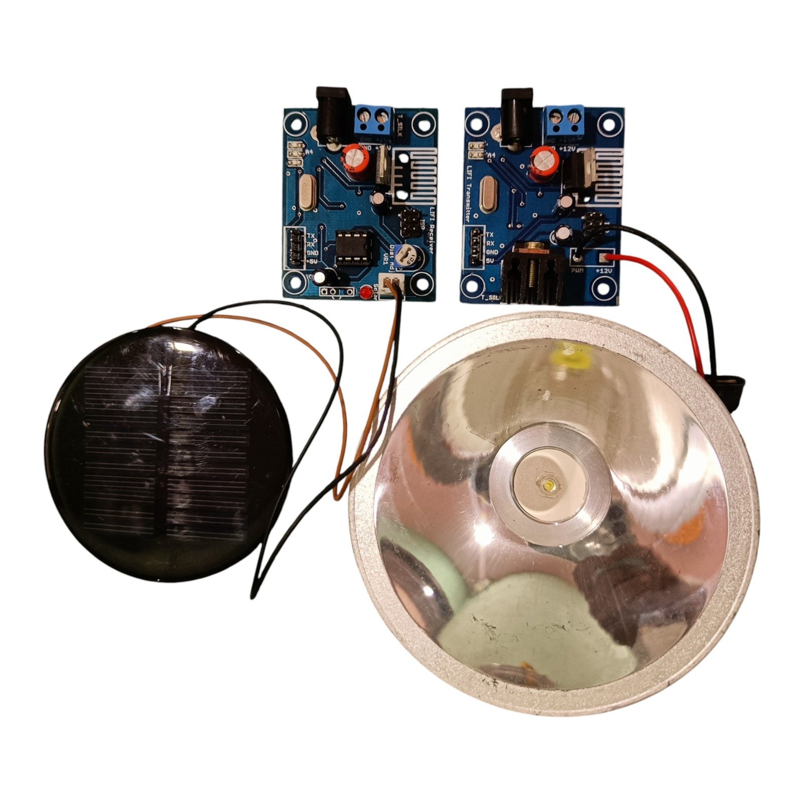
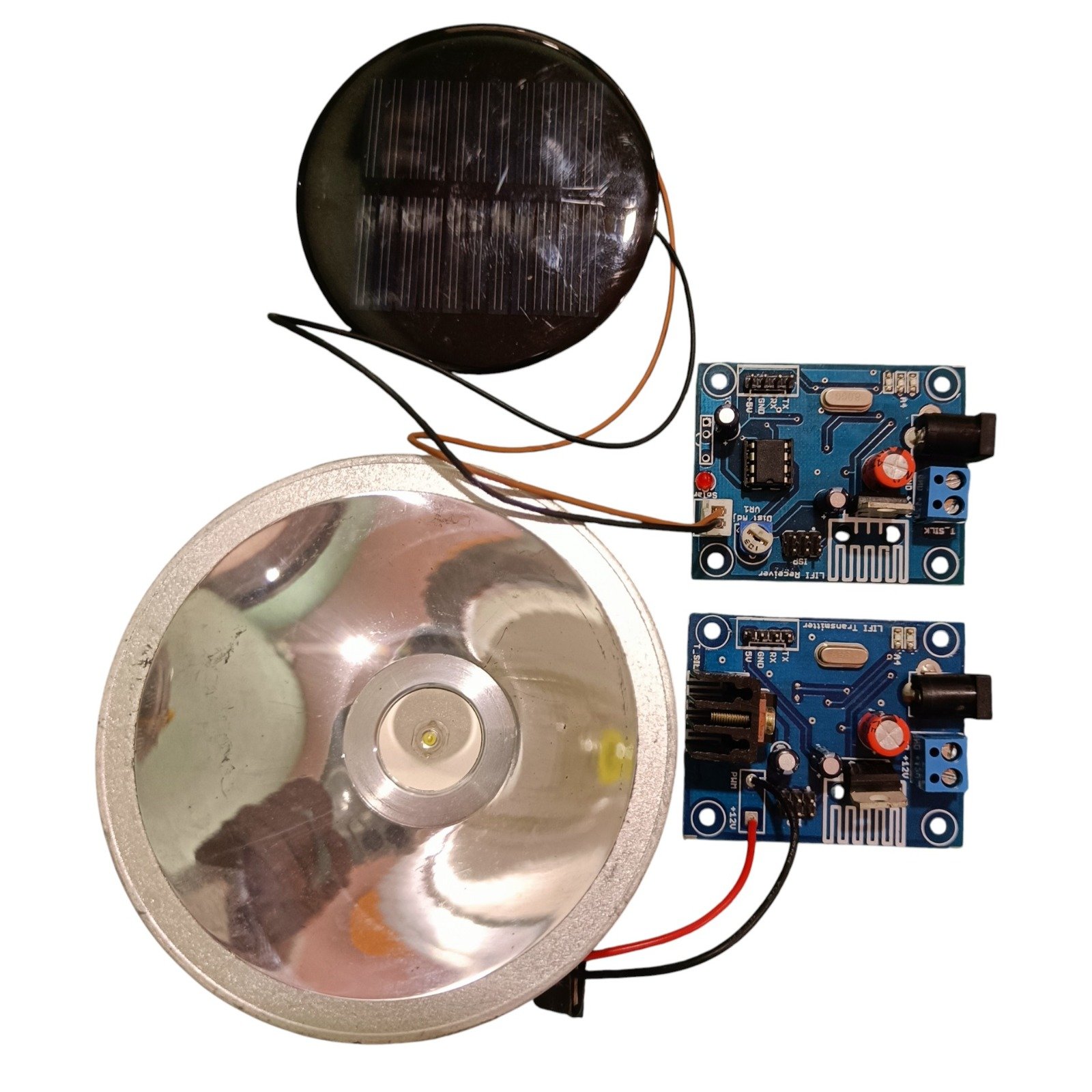
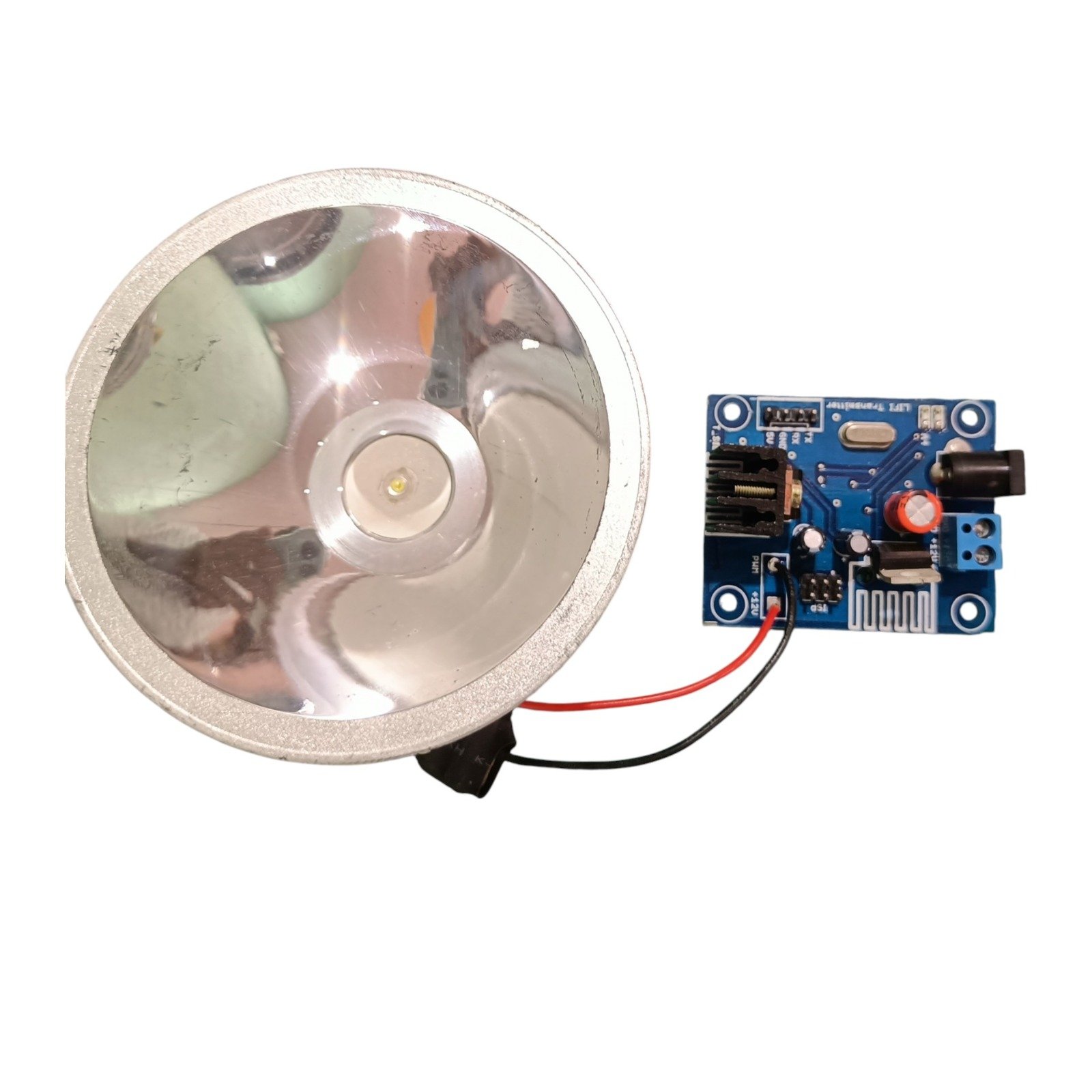
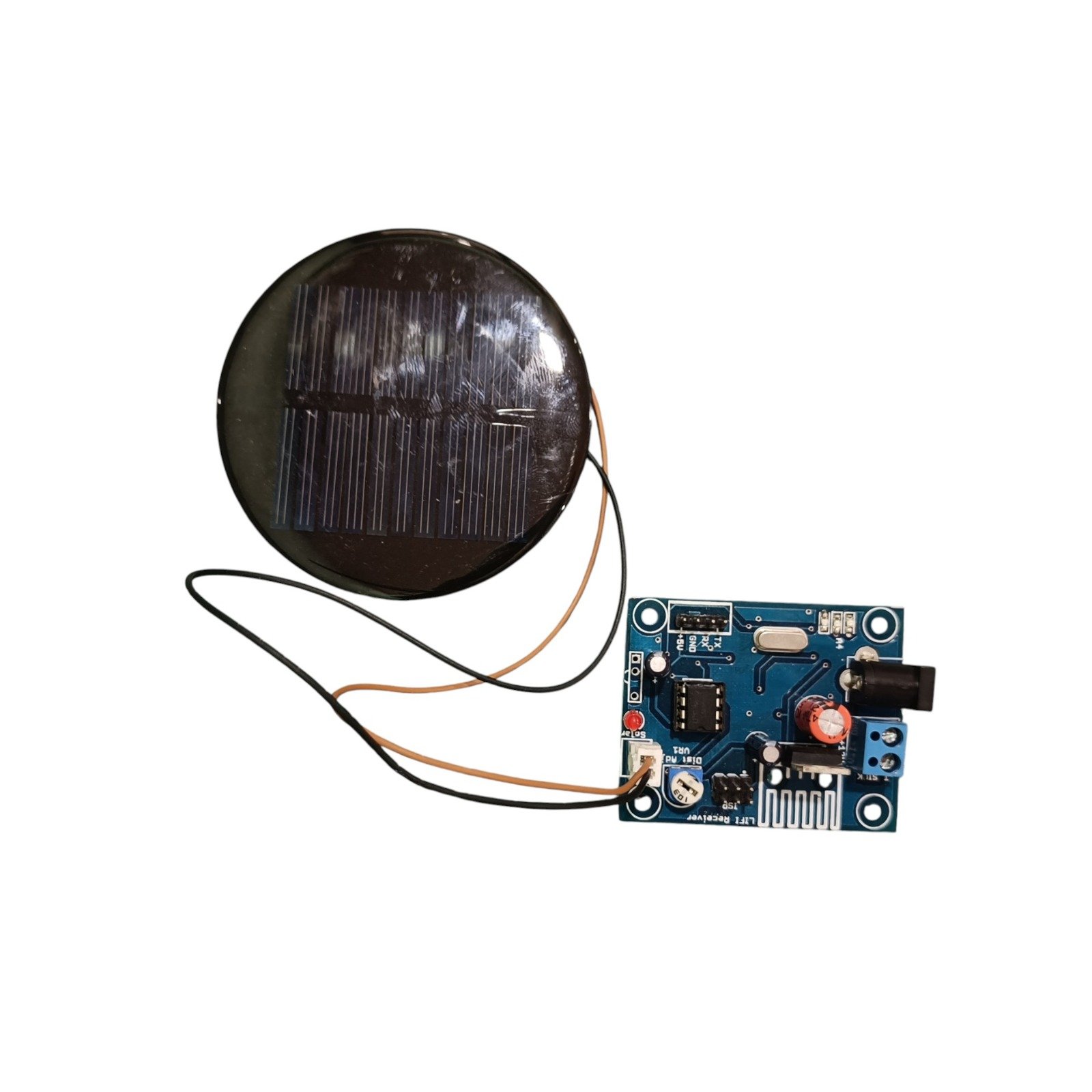
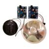
The system consists of a Li-Fi transmitter module and a Li-Fi receiver module. The transmitter modulates data onto visible light, while the receiver detects the optical signal and converts it back into serial data for the connected controller or electronic system.
The module is designed for a communication range of approximately 8 to 10 feet under suitable clear-path conditions. The receiver includes an adjustable trim potentiometer, allowing users to tune the receiver sensitivity according to ambient lighting and installation conditions.
Operating at a 9600 bps baud rate, the module is suitable for reliable point-to-point serial data communication between compatible devices. Since the communication is based on visible light, the signal is generally confined to the illuminated line-of-sight path rather than propagating through walls like typical RF signals.
Features
- Visible Light Communication (VLC) technology
- Wireless data transmission using LED light
- Point-to-point optical communication
- Communication range of approximately 8–10 feet under suitable conditions
- 9600 bps communication speed
- Adjustable receiver sensitivity
- Onboard trim potentiometer for receiver calibration
- Reduced dependence on RF communication
- Useful in RF-sensitive environments
- Compact transmitter and receiver modules
- Suitable for serial data transfer
- Line-of-sight communication
- Useful for indoor and specialized communication applications
Specifications
| Parameter | Specification |
|---|---|
| Product Type | Li-Fi / Visible Light Communication Module |
| Technology | Li-Fi / VLC |
| Communication Type | Point-to-Point Wireless |
| Baud Rate | 9600 bps |
| Transmission Range | 8–10 Feet (Optimal) |
| Communication Method | Visible Light |
| Receiver Calibration | Adjustable Variable Resistor / Trim Pot |
| Interference | Generally resistant to EMI/RFI; affected by ambient optical light |
| Communication Path | Line-of-Sight |
| Modules Included | 1 Transmitter + 1 Receiver |
Working Principle
The Li-Fi transmitter receives serial data from a connected electronic system and modulates the intensity of an LED at a high frequency. The rapid light modulation is used to encode the data without producing noticeable changes in the visible illumination.
The receiver detects these rapid changes in light intensity and converts them back into electrical serial data. The restored data can then be read by a microcontroller, computer, or other compatible electronic system.
Because the communication depends on the optical path between the transmitter and receiver, proper alignment is important for reliable operation.
Optical Communication
Unlike conventional Wi-Fi or Bluetooth systems that use radio waves, this module uses visible light as the transmission medium.
The optical nature of the system provides several advantages:
- Communication is directional
- The signal is primarily limited to the illuminated area
- It does not rely on conventional RF transmission
- It can be useful in environments sensitive to radio-frequency interference
- It can provide localized communication within a defined optical path
Actual performance depends on lighting conditions, transmitter power, receiver sensitivity, distance, alignment, and environmental factors.
Receiver Sensitivity Adjustment
The receiver includes an onboard trim potentiometer that can be used to adjust sensitivity.
This adjustment can help compensate for:
- Ambient lighting
- Distance between modules
- Indoor illumination
- Background light
- Receiver alignment
To achieve stable communication, slowly adjust the trim potentiometer while observing the received serial data until the output becomes reliable.
Typical Application Scenarios
Medical and Healthcare
Suitable for research and specialized communication applications where RF communication may need to be minimized. Actual use in medical environments should be evaluated according to applicable equipment and safety requirements.
Aviation and RF-Sensitive Environments
Visible-light communication can be explored for localized data transfer in environments where RF usage is restricted or undesirable.
Hazardous Environments
Optical communication can be useful for specific applications where RF communication is undesirable. Suitability for hazardous locations depends on the complete system design and applicable safety certifications.
Indoor Navigation and Robotics
The transmitter can be installed with a light source or positioning point to provide localized optical data to robots or handheld devices equipped with the receiver.
Underwater Communication
Visible light can be considered for short-range underwater data communication because radio waves do not propagate well through water. Actual range depends strongly on water clarity, optical power, alignment, and the environment.
Applications
- Li-Fi communication projects
- Visible light communication
- Wireless serial communication
- RF-free communication experiments
- Robotics communication
- Indoor navigation
- Optical data transfer
- Educational VLC projects
- Embedded wireless communication
- Industrial communication prototypes
- Underwater communication experiments
- Smart lighting communication research
- Point-to-point optical links
- IoT communication prototypes
- Laboratory communication systems
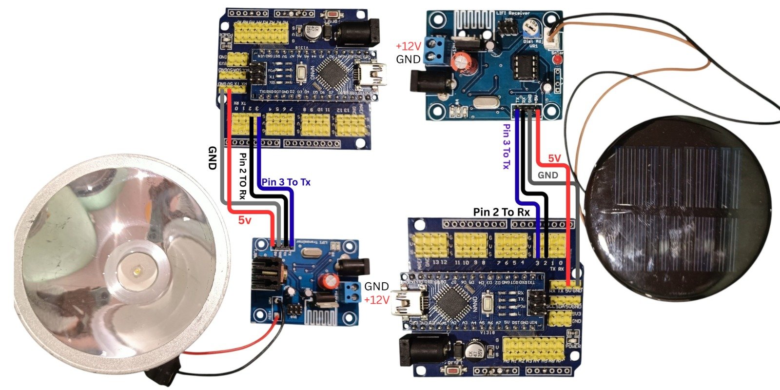
Connection Example
The transmitter can be connected to a suitable serial-data source such as a microcontroller or development board. The receiver can then be connected to another compatible serial interface to recover the transmitted data.
Package Includes
- 1 × Li-Fi Transmitter Module
- 1 × Li-Fi Receiver Module with Adjustable Trim Pot
Product Disclaimer
Product images are shown for illustrative and representational purposes only. The actual transmitter and receiver modules may vary slightly in PCB colour, component placement, connector arrangement, dimensions, LED appearance, or other visual details depending on the manufacturing batch.
Communication range and reliability are affected by ambient lighting, sunlight, distance, optical alignment, obstructions, receiver sensitivity, and installation conditions. The stated 8–10 foot range should be considered an approximate optimal range rather than a guaranteed operating distance in all environments.
The module is intended for development, experimentation, prototyping, and suitable communication applications. Specialized environments such as medical, aviation, hazardous, or underwater applications require independent system-level validation and appropriate certification where applicable.
Important Notes
Line-of-Sight Requirement
For best performance, keep a clear optical path between the transmitter LED and receiver sensor. Objects blocking or partially obstructing the light path can reduce communication reliability.
Receiver Calibration
Use a small screwdriver to adjust the receiver’s trim potentiometer slowly until the serial output becomes stable.
Ambient Light
Strong sunlight and other intense light sources can affect the receiver. For best performance, reduce direct exposure to bright ambient light.
Maximum Range
For approximately 10-foot communication, align the transmitter and receiver directly with each other and minimize obstructions and excessive ambient light.
Baud Rate
The module is optimized for 9600 bps serial communication. Use compatible serial settings on both the transmitting and receiving systems.
Frequently Asked Questions
1. What is this Li-Fi module used for?
It is used for wireless serial data transmission through visible light between a transmitter and receiver.
2. What is the communication range?
The specified optimal communication range is approximately 8–10 feet under suitable clear-path conditions.
3. What baud rate does it support?
The module is specified for 9600 bps serial communication.
4. Does it use Wi-Fi or Bluetooth?
No. The module uses visible light communication rather than conventional Wi-Fi or Bluetooth radio communication.
5. Does the receiver have sensitivity adjustment?
Yes. The receiver includes an onboard trim potentiometer for sensitivity calibration.
6. Can I connect it to Arduino?
Yes. It can be used with Arduino and other compatible controllers that support serial communication.
7. Can I use it with ESP32?
Yes. The transmitter and receiver can be integrated with ESP32 systems using suitable serial connections and voltage levels.
8. Does it require line of sight?
Yes. A clear optical path between the transmitter and receiver provides the best communication performance.
9. Can sunlight affect the module?
Yes. Strong ambient light, especially direct sunlight, can affect receiver performance and reduce communication reliability.
10. Can it work through walls?
No. The system relies on visible-light line-of-sight communication and is not designed to transmit data through walls like RF systems.
11. Can it be used underwater?
It can be used for experimental short-range underwater optical communication, but actual performance depends heavily on water clarity, optical alignment, depth, and environmental conditions.
12. Is the transmitter LED included?
Yes. The package includes one Li-Fi transmitter module.
13. Is the receiver included?
Yes. The package includes one Li-Fi receiver module with an adjustable trim potentiometer.
14. How can I improve the transmission range?
Keep the transmitter and receiver directly aligned, minimize ambient light interference, maintain a clear path, and adjust the receiver trim potentiometer for stable operation.
15. Can this module replace Wi-Fi?
No. It is a specialized point-to-point optical communication system intended for suitable applications and is not a general-purpose replacement for Wi-Fi networks.Only logged in customers who have purchased this product may leave a review.


Reviews
There are no reviews yet