
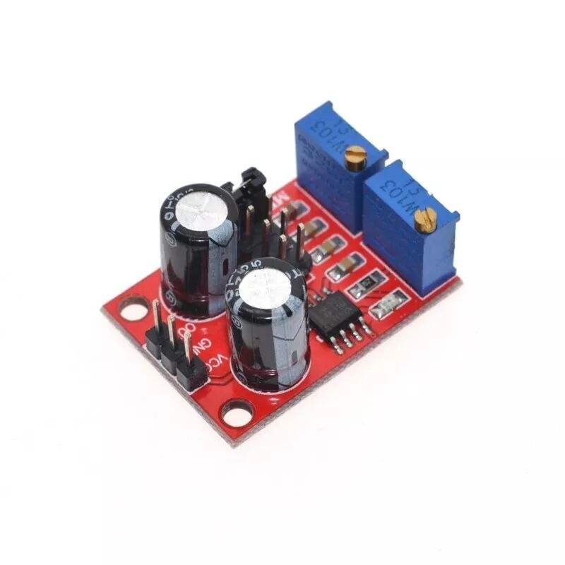
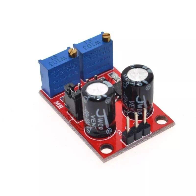
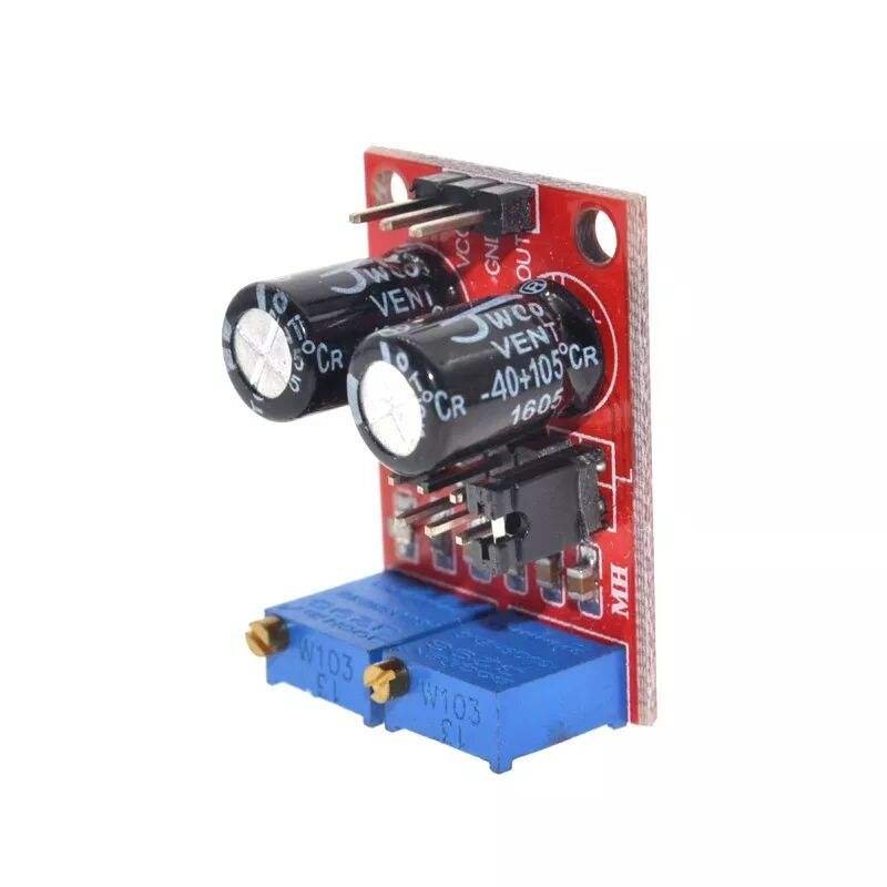
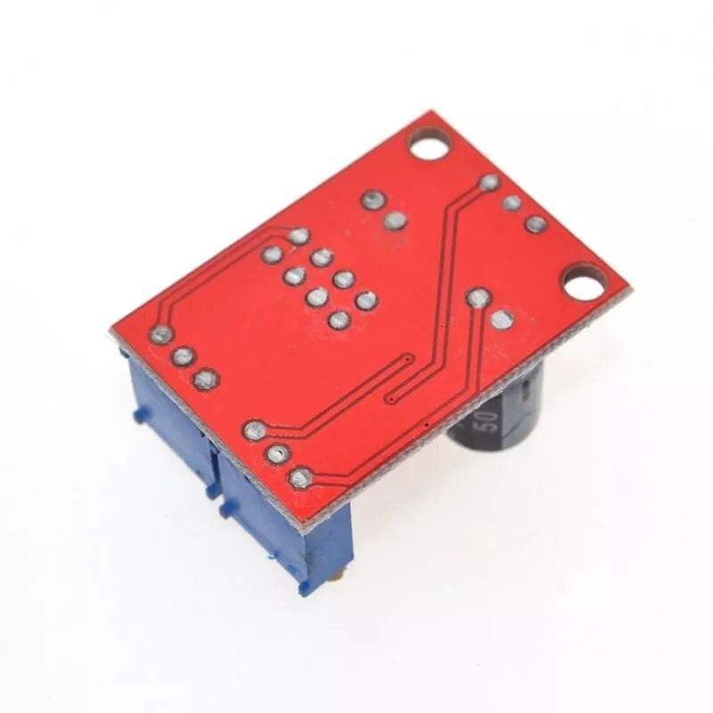
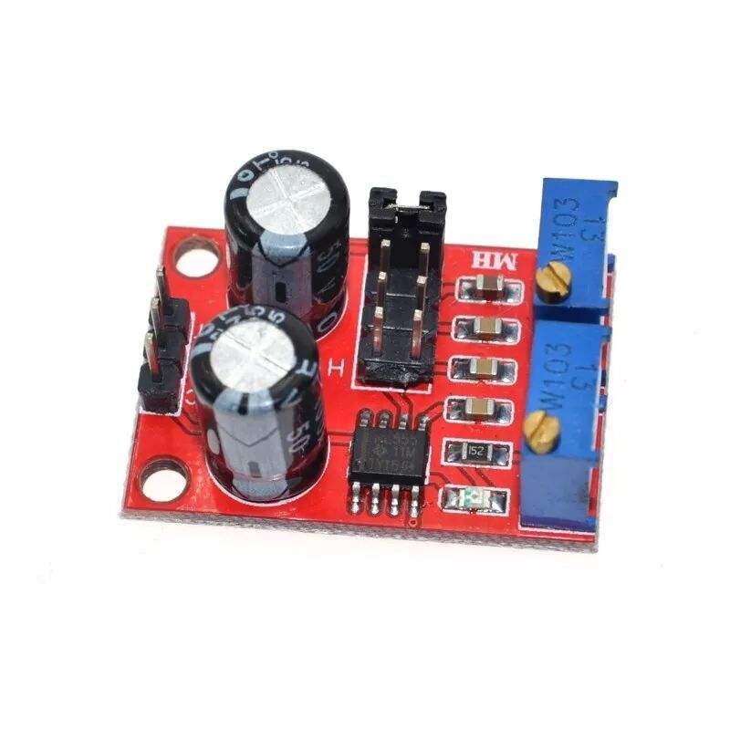
NE555 Pulse Adjustable Square Wave Signal Generator Module
₹50.74 incl. GST (₹43.00 + GST)
The NE555 Pulse Adjustable Square Wave Signal Generator Module is a compact signal generator based on the NE555 timer IC, designed to produce adjustable pulse, square-wave, and rectangular signals. It supports a wide 1Hz–200kHz frequency range with four selectable ranges and adjustable duty cycle. Operating from 5V–15V DC, it features an onboard LED indicator and provides a compact 31 × 22mm design. Ideal for frequency testing, PWM experiments, timing circuits, signal generation, Arduino projects, and DIY electronics.
The NE555 Pulse Adjustable Square Wave Signal Generator Module is a compact and versatile signal-generation board based on the popular NE555 timer IC. It is designed to generate adjustable pulse, square-wave, and rectangular-wave signals for electronics testing, timing, frequency generation, PWM experiments, and DIY circuit development.
With a compact size of approximately 31 × 22mm, the module can be easily integrated into breadboard projects, test setups, embedded systems, and electronic prototypes. It operates from a 5V to 15V DC supply and provides an adjustable output frequency across a wide range from approximately 1Hz to 200kHz.
The module features multiple frequency ranges that can be selected according to the required application. The frequency can be adjusted using the onboard controls, while the output duty cycle can also be fine-tuned. However, frequency and duty cycle are not independently adjustable, so changing the duty cycle may also change the output frequency.
An onboard LED output indicator provides a convenient visual indication of signal activity. The module is suitable for generating test signals and timing pulses for various electronic circuits.
Features
- Based on NE555 timer IC
- Adjustable pulse and square-wave output
- Rectangular-wave signal generation
- Adjustable output frequency
- Frequency range from approximately 1Hz to 200kHz
- Four selectable frequency ranges
- Adjustable duty cycle
- Output LED indicator
- Compact 31 × 22mm design
- Operates from 5V–15V DC
- Suitable for signal testing and circuit development
- Useful for PWM and timing experiments
- Suitable for DIY electronics projects
- Ideal for breadboard and prototype applications
- Simple and easy-to-use design
Specifications
| Parameter | Specification |
|---|---|
| Product Type | Pulse / Square Wave Signal Generator Module |
| Main IC | NE555 |
| Input Voltage | 5V–15V DC |
| Input Current | Up to approximately 100mA |
| Frequency Range | Approximately 1Hz–200kHz |
| Output Type | Square / Rectangular Wave |
| Output Amplitude | Approximately 4.2V–11.4V V-PP* |
| Maximum Output Current | Approx. 15mA @ 5V / 35mA @ 12V* |
| Frequency Adjustment | Adjustable |
| Duty Cycle | Adjustable |
| Frequency Ranges | 1–50Hz / 50Hz–1kHz / 1–10kHz / 10–200kHz |
| Indicator | Output LED |
| Dimensions | Approximately 31 × 22mm |
*Output amplitude and current depend on the supply voltage and operating conditions.
Design and Construction
The module uses the NE555 timer IC as its primary signal-generation component. The compact PCB includes the timing components and adjustment controls required to generate an adjustable rectangular waveform.
Its small form factor makes it convenient for electronics laboratories, breadboard experiments, signal testing, and embedded prototypes. The onboard LED provides visual feedback when the output signal is active.
The module provides multiple selectable frequency ranges, allowing users to choose a suitable range before fine-tuning the desired frequency.
Working Principle
The NE555 timer operates as an oscillator to continuously generate a rectangular or square-wave output signal. The output frequency is determined by the timing resistor and capacitor values.
The approximate frequency relationship is based on:
T = 0.7 × (RA + 2RB) × C
where:
- T = Signal period
- RA = Timing resistance
- RB = Adjustable timing resistance
- C = Timing capacitance
The module uses different capacitor settings for its selectable frequency ranges. Adjusting the timing resistance changes the charging and discharging time of the capacitor, thereby changing the output frequency.
The duty cycle can also be fine-tuned, although frequency and duty cycle are not completely independent. Changing the duty cycle may also cause a change in the output frequency.
Frequency Ranges
The module provides four selectable frequency ranges:
| Range | Frequency |
|---|---|
| LF | Approximately 1Hz–50Hz |
| IF | Approximately 50Hz–1kHz |
| High Frequency | Approximately 1kHz–10kHz |
| HF | Approximately 10kHz–200kHz |
The actual frequency range may vary slightly depending on component tolerances, supply voltage, adjustment position, and operating conditions.
Output Signal
The module generates a square/rectangular waveform suitable for applications that require a periodic digital-like signal.
The output amplitude depends on the input supply voltage. The stated output amplitude is approximately 4.2V to 11.4V V-PP, depending on the supplied voltage.
The maximum stated output current is approximately:
- 15mA at 5V supply
- 35mA at 12V supply
For loads requiring higher current, an external transistor, MOSFET, driver, or buffer circuit should be used instead of connecting the load directly to the module output.
LED Indicator
The onboard LED provides a simple visual indication of output activity.
At lower frequencies, the LED may visibly flash as the output changes. At higher frequencies, the LED may appear continuously illuminated or its brightness may change depending on the frequency and signal conditions.
Applications
- Square-wave signal generation
- Pulse generation
- Frequency testing
- PWM experiments
- Timing circuit testing
- Digital circuit testing
- Microcontroller signal testing
- Sensor signal simulation
- Motor-control experiments
- Clock signal generation
- Relay and switching experiments
- Audio-frequency experiments
- Electronics laboratory testing
- Breadboard prototyping
- DIY electronics projects
- Educational electronics
- Embedded-system development
- Frequency-response testing
- Signal injection
- General-purpose waveform generation
Advantages
- Wide adjustable frequency range
- Four selectable frequency ranges
- Compact size
- Simple NE555-based design
- Adjustable duty cycle
- Visual output indication
- Wide 5V–15V supply range
- Easy to integrate into prototype circuits
- Suitable for beginners and electronics enthusiasts
Package Includes
- 1 × NE555 Pulse Adjustable Square Wave Signal Generator Module
Product Disclaimer
Product images are for illustrative and representational purposes only. The actual product may vary slightly in colour, PCB layout, component placement, dimensions, markings, or overall appearance depending on the manufacturing batch.
The module size is manually measured and may have an approximately 1–5mm measurement tolerance.
The stated output voltage, frequency, current, and frequency ranges are approximate and may vary depending on supply voltage, component tolerances, load, temperature, and adjustment settings.
The output current is limited. Do not directly connect high-current loads such as motors or other power-hungry devices to the signal output. Use an appropriate external driver circuit when required.
Frequently Asked Questions (FAQs)
1. What is the NE555 Signal Generator Module used for?
It is used to generate adjustable pulse, square-wave, and rectangular signals for testing, timing, PWM, and electronics projects.
2. Which IC is used on the module?
The module uses the popular NE555 timer IC.
3. What is the operating voltage?
The module operates from 5V to 15V DC.
4. What frequency range does it support?
It provides an adjustable frequency range of approximately 1Hz to 200kHz.
5. How many frequency ranges are available?
There are four selectable ranges:
- LF: 1Hz–50Hz
- IF: 50Hz–1kHz
- High Frequency: 1kHz–10kHz
- HF: 10kHz–200kHz
6. Can the output frequency be adjusted?
Yes. The output frequency can be adjusted using the onboard controls.
7. Can the duty cycle be adjusted?
Yes. The duty cycle can be fine-tuned, but frequency and duty cycle are not independently adjustable. Changing the duty cycle may also change the frequency.
8. What type of waveform does it generate?
The module generates a square-wave/rectangular pulse waveform.
9. What is the output voltage amplitude?
The stated output amplitude is approximately 4.2V–11.4V V-PP, depending on the input supply voltage.
10. What is the maximum output current?
The stated output capability is approximately 15mA at 5V and 35mA at 12V, depending on operating conditions.
11. Does the module have an LED indicator?
Yes. The onboard LED indicates output activity. At low frequencies, the LED may visibly flash.
12. Can I use this module with Arduino?
Yes. It can be used as an external pulse or square-wave source for compatible Arduino projects and experiments.
13. Can it be used for PWM experiments?
Yes. Its adjustable duty cycle makes it suitable for basic PWM and pulse-generation experiments.
14. Can it be used for frequency testing?
Yes. It can generate adjustable test signals for electronics testing and signal measurement.
15. Can it drive a motor directly?
It is not recommended to connect a motor directly to the signal output because the module has limited output current. Use a suitable transistor, MOSFET, or motor-driver circuit.
16. Can it drive high-current loads?
No. High-current loads should be controlled through an appropriate external driver or buffer circuit.
17. What is the size of the module?
The module is approximately 31mm × 22mm. Manual measurement may have a small tolerance.
18. What determines the output frequency?
The frequency is determined by the timing resistors and capacitor used in the NE555 oscillator circuit.
19. Can the module generate very low frequencies?
Yes. The LF range supports frequencies starting at approximately 1Hz.
20. Can it generate high-frequency signals?
Yes. The HF range supports frequencies up to approximately 200kHz.
21. Is the frequency exactly accurate?
The actual frequency may vary slightly due to component tolerances, supply voltage, temperature, load, and adjustment settings.
22. What are the common applications?
It can be used for signal generation, frequency testing, PWM experiments, timing circuits, sensor simulation, digital circuit testing, Arduino projects, and electronics prototyping.
23. Is it suitable for beginners?
Yes. Its simple NE555-based design and adjustable controls make it suitable for students, hobbyists, and electronics enthusiasts.
24. What is included in the package?
The package includes 1 × NE555 Pulse Adjustable Square Wave Signal Generator Module.
25. Is the actual product exactly the same as shown in the images?
No. Product images are for representation only, and the actual module may vary slightly in colour, PCB layout, component placement, markings, dimensions, or appearance depending on the manufacturing batch.
Only logged in customers who have purchased this product may leave a review.


Reviews
There are no reviews yet