
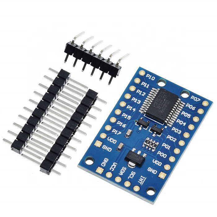
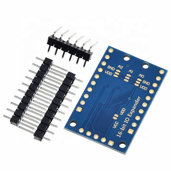
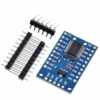
PCF8575 Remote 16-Bit I2C I/O Expander Module
₹164.02 incl. GST (₹139.00 + GST)
9 in stock
Expand your microcontroller with 16 digital I/O pins through I2C using only SDA and SCL. Suitable for buttons, LEDs, relays and control circuits.
The PCF8575 Remote 16-Bit I2C I/O Expander Module adds up to 16 digital input/output pins to a microcontroller through the two-wire I2C interface. Only the SDA and SCL pins of the controller are required, making it useful when the available GPIO pins are limited.
The module is based on the PCF8575, which provides a 16-bit quasi-bidirectional I/O port. Each port can be used for reading digital inputs or controlling digital outputs. Unlike conventional GPIO expanders, the PCF8575 does not use separate input and output direction registers. A pin is normally written HIGH before it is used as an input.
An open-drain interrupt output is available for detecting a change on an input pin. This allows the microcontroller to respond to button presses, switches or sensor status changes without continuously polling every I/O pin.
This module version also includes a 3.3V level-conversion circuit. When the VCC–VDD solder pad is left open, the PCF8575-side logic operates at 3.3V. When the pad is soldered, the PCF8575-side voltage follows the applied VCC. This feature should be verified on the received module before connection because PCB layouts can vary between manufacturing batches.
The module is suitable for Arduino, ESP32, ESP8266, STM32, Raspberry Pi and other controllers that support I2C communication.
Features
- Adds 16 remote digital I/O pins
- Uses only SDA and SCL for communication
- I2C and SMBus-compatible interface
- 16-bit quasi-bidirectional I/O port
- Each port can be used as an input or output
- Open-drain interrupt output
- Onboard 3.3V level-conversion circuit
- VCC–VDD solder pad for voltage-level selection
- Supports multiple modules on the same I2C bus
- Suitable for LEDs, buttons, switches and control signals
- Compatible with 3.3V and 5V microcontroller systems
- Reduces microcontroller GPIO requirements
Specifications
| Parameter | Specification |
|---|---|
| Main IC | PCF8575 |
| Interface | I2C / IIC / SMBus |
| Number of I/O Pins | 16 |
| Port Type | Quasi-bidirectional |
| IC Operating Voltage | 2.5V to 5.5V |
| Maximum I2C Clock | Up to 400kHz |
| Interrupt Output | Open-drain, active LOW |
| Address Selection | A0, A1 and A2, when exposed on the module |
| Common Address Range | 0x20 to 0x27 |
| Logic-Level Circuit | Onboard 3.3V level conversion |
| Communication Pins | SDA and SCL |
| Typical Applications | Buttons, LEDs, relay-control signals and digital sensors |
The PCF8575 IC is specified for operation from 2.5V to 5.5V and supports I2C communication rates up to 400kbit/s.
Pinout and Wiring
The exact printed labels may differ slightly between module versions.
| Pin | Function |
|---|---|
| VCC | External module supply input |
| GND | Ground |
| SDA | I2C serial data |
| SCL | I2C serial clock |
| INT | Active-LOW open-drain interrupt output |
| A0 | I2C address-selection bit 0 |
| A1 | I2C address-selection bit 1 |
| A2 | I2C address-selection bit 2 |
| P0–P15 | Sixteen quasi-bidirectional digital I/O pins |
| VDD | PCF8575-side supply or logic-level reference, depending on module design |
Basic Arduino Connection
| PCF8575 Module | Arduino Uno/Nano |
|---|---|
| VCC | 5V or suitable module supply |
| GND | GND |
| SDA | A4 |
| SCL | A5 |
| INT | Optional digital input |
| P0–P15 | Buttons, LEDs or control signals |
Basic ESP32 Connection
| PCF8575 Module | ESP32 |
|---|---|
| VCC | According to the module’s selected voltage configuration |
| GND | GND |
| SDA | GPIO21 by default |
| SCL | GPIO22 by default |
| INT | Any suitable digital input |
| P0–P15 | Digital devices |
ESP32 I2C pins can be changed in software, so GPIO21 and GPIO22 are only commonly used defaults.
VCC–VDD Solder-Pad Operation
Pad Not Soldered
The PCF8575-side logic is configured for 3.3V operation through the module’s onboard level-conversion arrangement.
Pad Soldered
VDD is connected to VCC, causing the PCF8575-side voltage to follow the applied VCC.
Inspect the solder pad and confirm the module circuit before powering it. Do not change the pad while the board is powered.
Important Output Behaviour
The PCF8575 has quasi-bidirectional ports rather than conventional push-pull GPIO outputs.
- Writing LOW makes the port actively pull the signal LOW.
- Writing HIGH releases the port and allows it to function as an input.
- The HIGH-level sourcing capability is limited.
- High-current devices must not be powered directly from an I/O pin.
Use a transistor, MOSFET, optocoupler or driver IC for relays, motors, solenoids, high-power buzzers or multiple LEDs.
Applications
- Expanding Arduino or ESP32 GPIO pins
- Reading multiple push buttons
- Reading limit switches
- Keypad interfacing
- LED indication systems
- Relay-board control
- Buzzer-control signals
- Home-automation systems
- Industrial status monitoring
- Robotics projects
- Alarm panels
- Digital sensor expansion
- Control-panel input expansion
Frequently Asked Questions
Does this module provide 16 additional GPIO pins?
Yes. It provides 16 quasi-bidirectional digital ports controlled over I2C.
Does it require 16 microcontroller pins?
No. Normal communication requires only SDA and SCL. The optional INT pin can use one additional microcontroller input.
Can each pin be used as either an input or output?
Yes, but the PCF8575 uses quasi-bidirectional ports. To use a port as an input, write HIGH to that port and then read its state. There is no conventional GPIO direction register.
Can it be used with ESP32?
Yes. The module’s level configuration must be suitable for 3.3V ESP32 logic. Check the VCC–VDD solder pad and the actual module circuit before connection.
Can it be used with Arduino Uno?
Yes. It can communicate with an Arduino through the A4 SDA and A5 SCL pins.
Can it directly operate a relay?
It should not directly power a relay coil. Use it only to control a transistor, MOSFET, relay-driver IC or a compatible relay module.
Can it directly drive a buzzer?
A small active buzzer may still require a driver depending on its current. A transistor driver is recommended to protect the PCF8575 output.
Can it generate PWM signals?
The PCF8575 does not contain hardware PWM outputs. Software-controlled switching through I2C may be possible, but it is not suitable for accurate or high-frequency PWM.
What is the purpose of the INT pin?
INT changes state when an input-port condition changes. It can alert the microcontroller without requiring continuous polling. Since it is open drain, it requires a pull-up resistor unless the module already includes one.
Can more than one module be connected?
Yes, where address-selection pins or pads A0, A1 and A2 are available. Different addresses must be selected to avoid an I2C address conflict.
What is the usual I2C address?
The normal PCF8575 address range is 0x20 to 0x27, depending on the A0, A1 and A2 settings.
Are the pins analog inputs?
No. The PCF8575 ports are digital input/output pins. They cannot measure analog voltage.
Downloads and Datasheet
- Official Texas Instruments PCF8575 datasheet
- Texas Instruments PCF8575 product information
- Official NXP PCF8575 datasheet
- NXP PCF8575 product information
Focus Keyword
Secondary Keywords
- PCF8575 I/O expander module
- 16-bit I2C GPIO expander
- I2C 16-channel digital expansion module
- Arduino GPIO expander module
- ESP32 I2C I/O expander
- PCF8575 IIC module
- 16-pin digital I/O expansion board
- SMBus I/O expander module
Product Disclaimer
Product Disclaimer: Product images are for reference purposes only. The actual PCB colour, dimensions, component placement, silkscreen printing, solder-pad configuration and pin labels may vary depending on the manufacturing batch.
The onboard 3.3V level-conversion circuit and VCC–VDD solder-pad behaviour are specific to this module design. Inspect the received module and confirm its circuit configuration before connecting it to a 3.3V or 5V controller. Do not assume that every PCF8575 breakout board uses the same voltage arrangement.
The PCF8575 outputs are quasi-bidirectional and have limited current-driving capability. Do not directly connect motors, relay coils, solenoids, high-current buzzers, high-power LEDs or other heavy loads. Use a suitable transistor, MOSFET, optocoupler or driver circuit.
This module does not provide analog inputs, galvanic isolation, overload protection or short-circuit protection. Incorrect wiring, reverse polarity, excessive voltage, I2C voltage mismatch, output overload or short circuits may damage the module and the connected controller.
Users must verify the operating voltage, I2C address, port behaviour and wiring before powering the circuit. All connected devices must share a common ground unless an appropriate isolation circuit is used.
This product is intended for educational, development, prototyping and general electronics applications. It is not certified for medical, automotive, aerospace, life-support or safety-critical systems. Robosap is not responsible for damage caused by improper wiring, excessive load, incorrect solder-pad configuration, electrostatic discharge or use outside the specified operating conditions.
Package Includes
- 1 × PCF8575 Remote 16-Bit I2C I/O Expander Module
Only logged in customers who have purchased this product may leave a review.



Reviews
There are no reviews yet